Installation, Operating & Maintenance Instructions
Series 650, DN 100 – 250 (I.D. 4" - 10")
VAT Vakuumventile AG, CH-9469 Haag, Switzerland
Tel ++41 81 771 61 61 Fax ++41 81 771 48 30 Email reception@vat.ch www.vatvalve.com
258550EE
2007-05-11
36/51
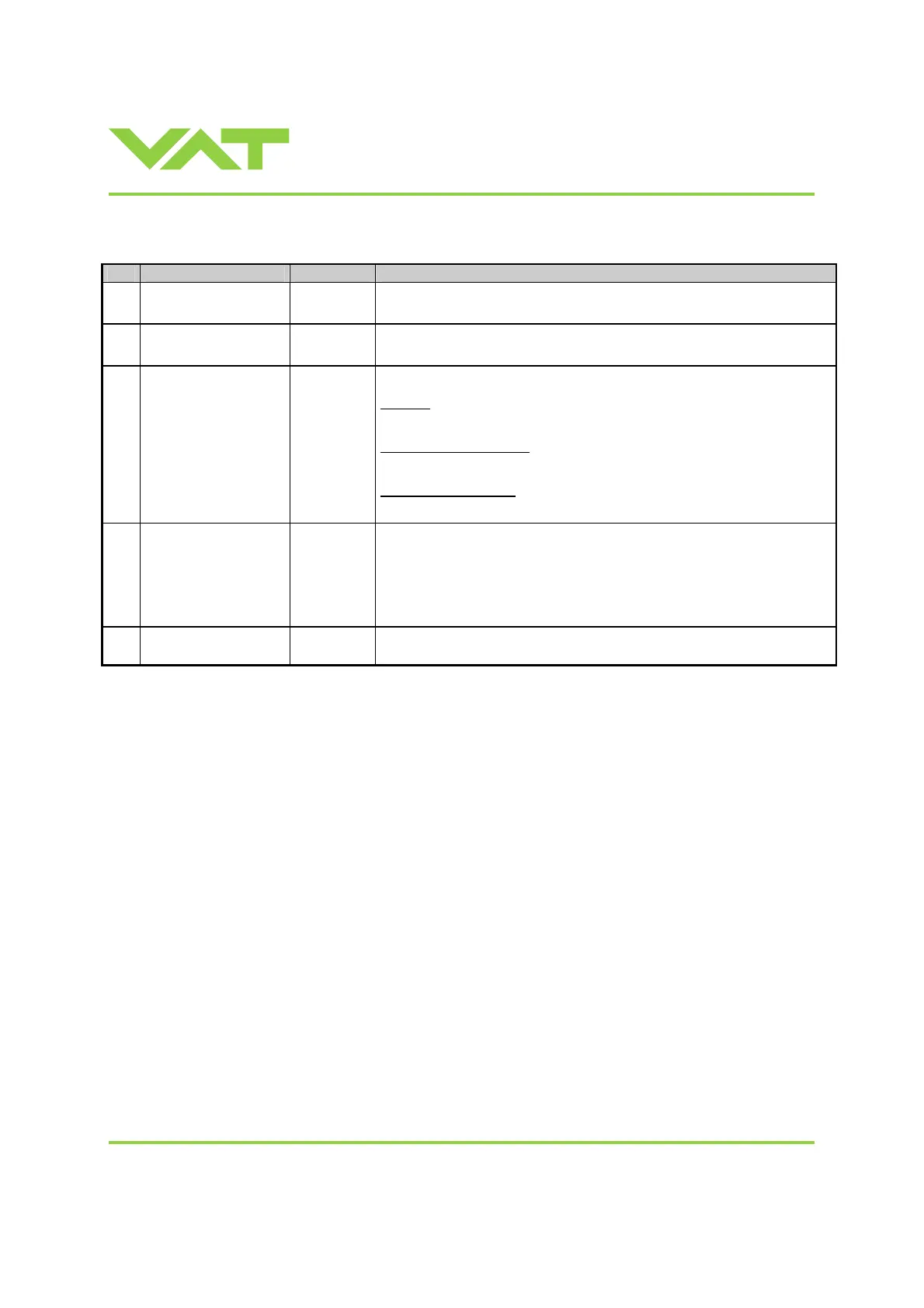
3.11.3 Digital outputs
Pin Function Signal type
Description
8
VALVE OPEN
Digital
output
1)
This output is active in all operation modes and indicates that the valve is
fully open.
9
VALVE CLOSED
Digital
output
1)
This output is active in all operation modes and indicates that the valve is
closed (isolated).
22
ALARM
Digital
output
1)
The meaning of the alarm output depends on the operation mode.
LEARN:
LEARN is not completed yet.
PRESSURE CONTROL:
Actual pressure is out of ±2% range of SETPOINT
POSTION CONTROL:
Actual position is out of ±0.1% range of SETPOINT
21 READY
Digital
output
1)
This signal indicates that the valve is ready for remote operation.
If this signal is not active the valve is in one of the following modes:
• Synchronization during power up
• Local operation via service port
• Safety mode. Refer to «3.1.3 Safety mode» for details.
20
COMMON
Digital
common
Common for all digital outputs.
1) Refer to «3.11.1 Schematics» for details about output circuit.
 Loading...


