EMR
3
Setup and Operation Manual Boot-Up Test Sequence
5
Boot-Up Test Sequence
When power is initiated to the Display Head, the screen will power up with a test sequence that satisfies the
requirements of the local Weights and Measures authority. The Display Head test sequence follows below:
• ROM TEST
• DATA BUS TEST (message not displayed)
• ADDRESS BUS TEST (message not displayed)
• RAM TEST
• CS TEST (message not displayed)
• NVRAM TEST
• INIT NVRAM
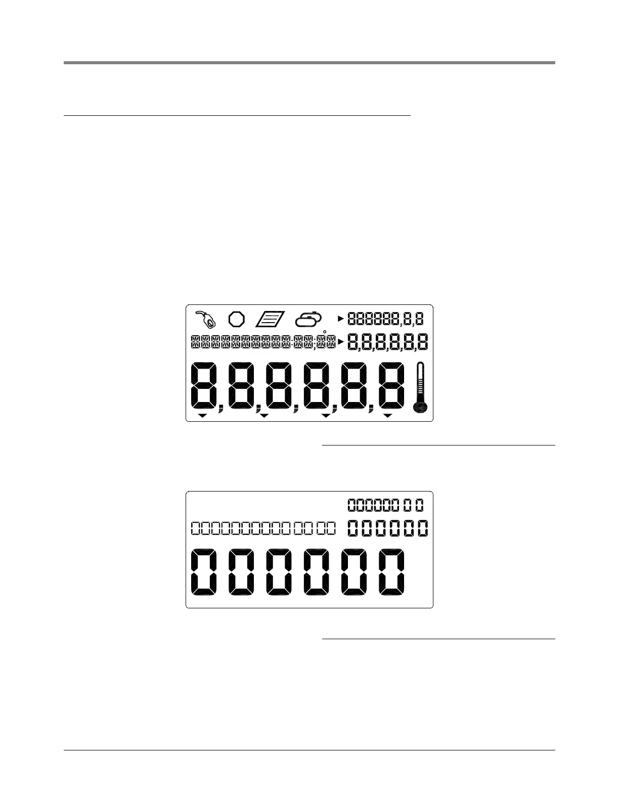
• All segments of the display are activated (see Figure 3):
Figure 3. All Segments Activated
• All zeros appear in the four display value fields (see Figure 4):
Figure 4. All Zeros Activated in the Display Fields
• On initial startup of EMR
3
Systems with two Display Heads, you must go to the Head Address Setup
(Figure 28 on page 26) and assign an unique Head Address for each Display Head. Because the factory default
Head Address is set to a “1”, one of the two Display Head’s addresses must be changed to a “2”. Caution!
Failure to do so will cause communication problems which will result in erratic operation.
 Loading...