30
6Setupwiththedisplayandadjustmentmodule
MINITRAC 31 • Foundation Fieldbus
41782-EN-211203
6 Set up with the display and adjustment
module
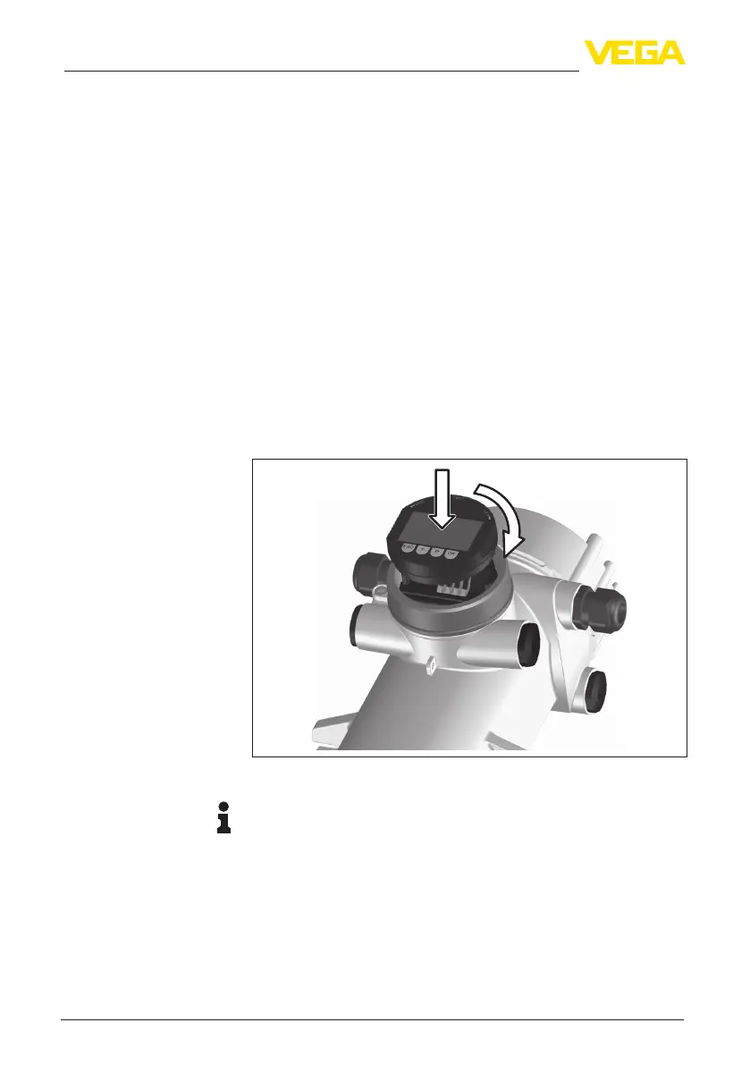
6.1 Insert display and adjustment module
The display and adjustment module can be inserted into the sensor
and removed again at any time. It is not necessary to interrupt the
voltage supply.
Proceedasfollows:
1. Unscrewthesmallhousingcover
2. Place the display and adjustment module in the desired position
ontheelectronics(youcanchooseanyoneoffourdierentposi-
tions-eachdisplacedby90°)
3. Press the display and adjustment module onto the electronics
and turn it to the right until it snaps in
4. Screwhousinglidwithinspectionwindowtightlybackon
Disassembly is carried out in reverse order.
Thedisplayandadjustmentmoduleispoweredbythesensor,anad-
ditional connection is not necessary.
1
2
Fig. 19: Insert display and adjustment module
Note:
Ifyouintendtoretrottheinstrumentwithadisplayandadjustment
moduleforcontinuousmeasuredvalueindication,ahigherlidwithan
inspection glass is required.
Mount/dismount display
and adjustment module
 Loading...