Vertiv | eSure™ Rectifier Module User Manual (UM1R483500e3) | Rev. H
OPERATION
AC Input Protection Device Requirements/Recommendations
Refer to the system documentation supplied with the system the rectifier is installed in.
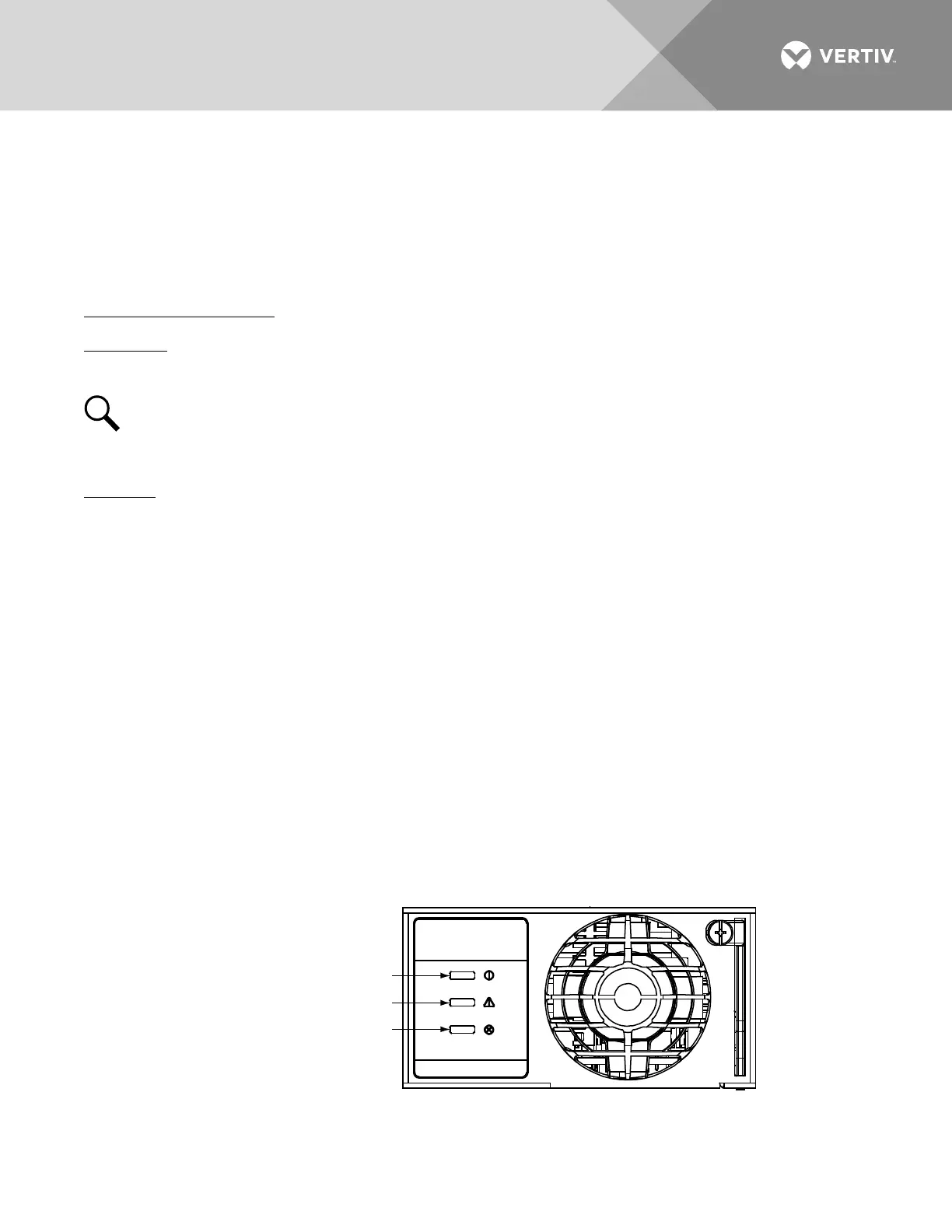
Local Indicators
Location and Identification: Refer to Figure 5.
Description: There are three (3) indicators located on the rectifier’s front panel. The functions of these
indicators are as shown in Table 6.
NOTE!
AC voltage must be present at the rectifier input terminals.
Rectifier High Voltage Shutdown and Lockout Restart
Procedure
1. Turn the power to the rectifier off or remove the rectifier, wait 30 seconds or more (until the LEDs on
the rectifier extinguish), then turn the power to the rectifier on or re-insert the rectifier.
Rectifier Current Limit
When setting total rectifier current limit, the set point to each rectifier is the total set point divided by the
number of rectifiers. For example, if the system contains five rectifiers and the current limit is set to 150 amps
then each rectifier has a current limit set point of 30 amps. If one or more rectifiers are removed or fail it will
take several seconds for the individual set points to the remaining rectifiers to be reset. In the example given, if
one rectifier is removed the current limit set point will drop to 120 amps (30 amps times four remaining
rectifiers) until the controller can send updated set points to the remaining rectifiers. This takes a couple
communication cycles (several seconds) after which each rectifier would have a new set point of 37.5 amps for
a total of 150 amps. The total current limit of the rectifiers should not be set such that the loss of the
redundant rectifiers will cause this temporary set point to drop below the actual maximum expected load. If
batteries are used on the rectifier output, the batteries should support the load until the current limit set points
can be re-established due to loss of a rectifier.
Figure 5:
Local Indicator Locations
Protection Indicator (Yellow)
Power Indicator (Green)
Alarm Indicator (Red)
R48-3500e3

 Loading...


