Vertiv™ NetSure™ 5100 Series -48 VDC Power System User Manual
Proprietary and Confidential © 2022 Vertiv Group Corp.
4 Maintenance
4.1 System Maintenance Procedures
It is recommended to perform the maintenance procedures listed in Table 4.1 every 6-months to ensure continual system operation.
Table 4.1 Maintenance Procedures to be Performed at 6-Month Intervals
Procedure Referenced In
Check ventilation openings for obstructions
such as dust, papers, manuals, etc.
--
Inspect and tighten all installer's
connections.
IM582137100
4.2 Adding a Module to an Existing Module Mounting Assembly
To increase system current capacity, a rectifier or solar converter module can easily be added to an existing module mounting
assembly that contains an empty rectifier module or solar converter module mounting position. Likewise, to increase subsystem
capacity, a -48 VDC to +24 VDC converter module can be added to a module mounting assembly that contains an empty -48 VDC to
+24 VDC converter module mounting position. Also, a -48 VDC to -58 VDC DC-DC converter module can be added to a module
mounting shelf that contains an empty -48 VDC to -58 VDC converter module mounting position.
Rectifier, solar converter, optional -48 VDC to +24 VDC converter modules, and optional -48 VDC to -58 VDC converter modules can
be inserted or removed with power applied (hot swappable).
Procedure
NOTE!
Each module locks into the module mounting assembly by means of a latch located on the bottom of the module.
The latch and module handle are interactive. Pushing the handle up into the module’s front panel causes the latch to extend
to the locking position; pulling the handle down out from the module’s front panel causes the latch to retract. See
Figure 4.3,
Figure 4.4, or Figure 4.5.
WARNING! To prevent damage to the latching mechanism, ensure the handle is in the open position when installing or
removing a module. NEVER hold the handle in the closed position when installing a module into a module mounting
assembly.
ALERT! The system can either have +24V DC-DC converters installed or -58V DC-DC converters installed. The system
cannot have both types of converters installed at the same time.
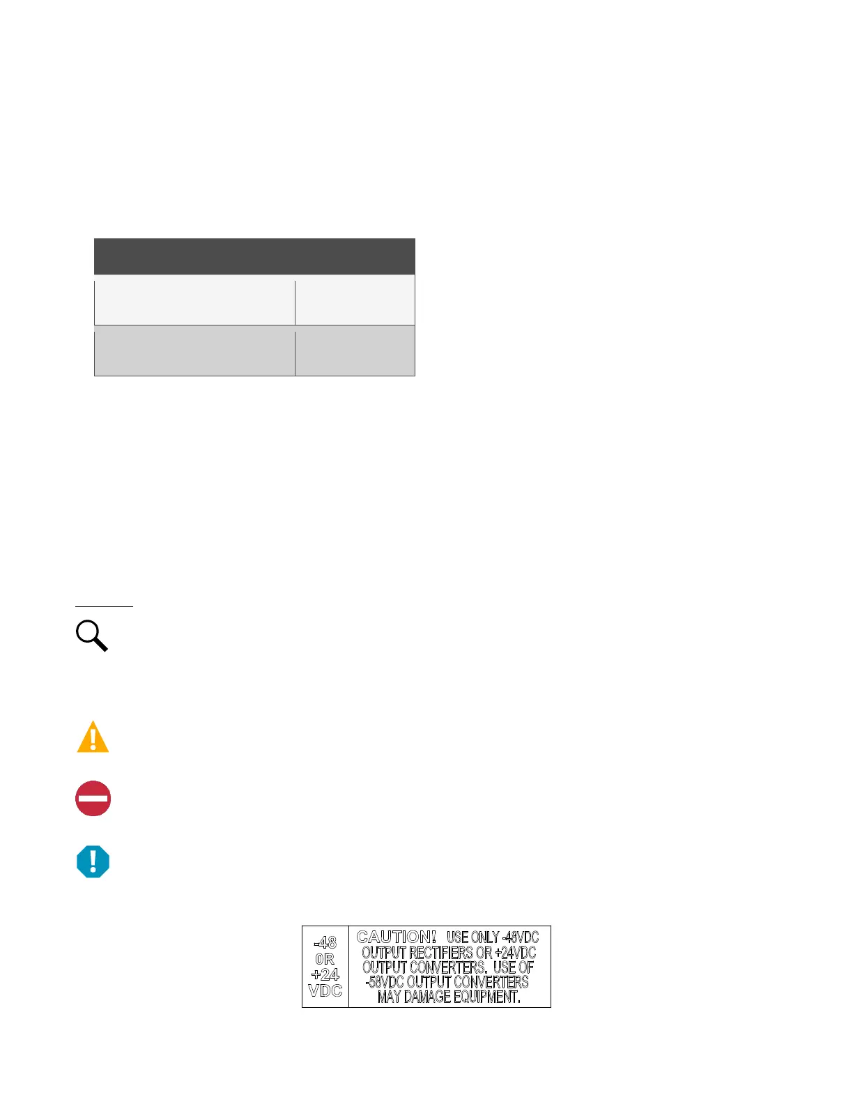
ALERT! The -48 VDC to +24 VDC converter modules must only be installed in a system position that accepts a +24V DC-DC
converter. Refer to labeling on the system’s module mounting shelf. A sample of this labeling is provided in Figure 4.1.
Figure 4.1 Sample Module Mounting Shelf Labeling

 Loading...


