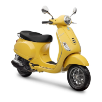
CHECKING REMOTE CONTROLS «A» OPER-
ATING AS CIRCUIT BREAKERS
1) Check that, given regular conditions, there is no
continuity between terminals 30 and 87.
2) Apply 12V voltage to power terminals 85 and 86
of the remote control.
3) With the remote control powered, check that
there is continuity between terminals 30 and 87.
4) If these conditions are not fulfilled, the remote
control is damaged and must be replaced.
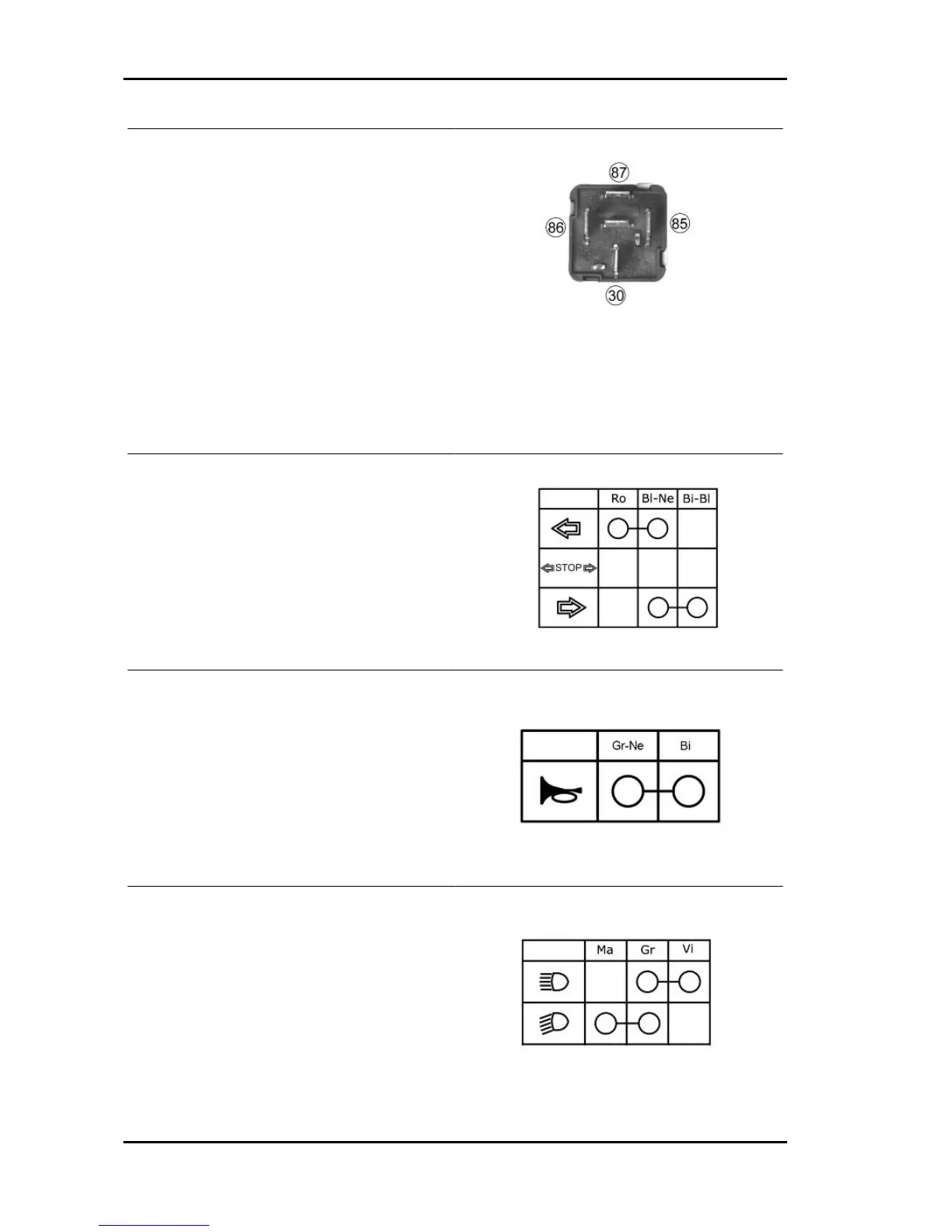
To check buttons and switches, check that, according to their position, the continuity of contacts is
correct as indicated in the following charts.
TURN INDICATOR SWITCH
HORN BUTTON
LIGHT SWITCH
Characteristics Vespa LX 125 - 150 i.e.
CHAR - 10
 Loading...