Vogt
®
VT Service Manual 2-7
Installation Instructions
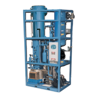
Power is supplied to the lowside through circuit breaker (CB1) located in the condensing unit control panel.
See diagram below.
FIGURE 2-7
Condensing Unit Circuit Breakers (200/230V)
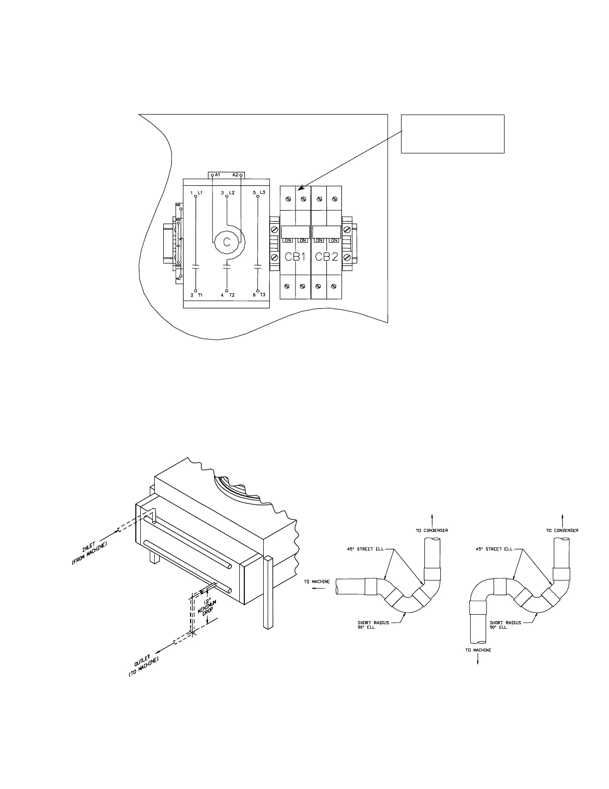
Air Cooled Condenser Installation (VT80 & VT100):
Ice making systems with remote condensers
are trapped internally. A trap leaving the compressor is not necessary. On vertical runs a short radius “P” trap
should be installed every 15’ to 20’ of vertical rise to facilitate oil flow. Horizontal runs should be sloped in
direction of refrigerant flow 1” for every 20’ of run. The condenser should be securely mounted in a place
capable of sustaining its weight.
FIGURE 2-8
Condenser Piping (VT80 & VT100) and Recommended Traps
Condensing unit control panel
to lowside unit
 Loading...