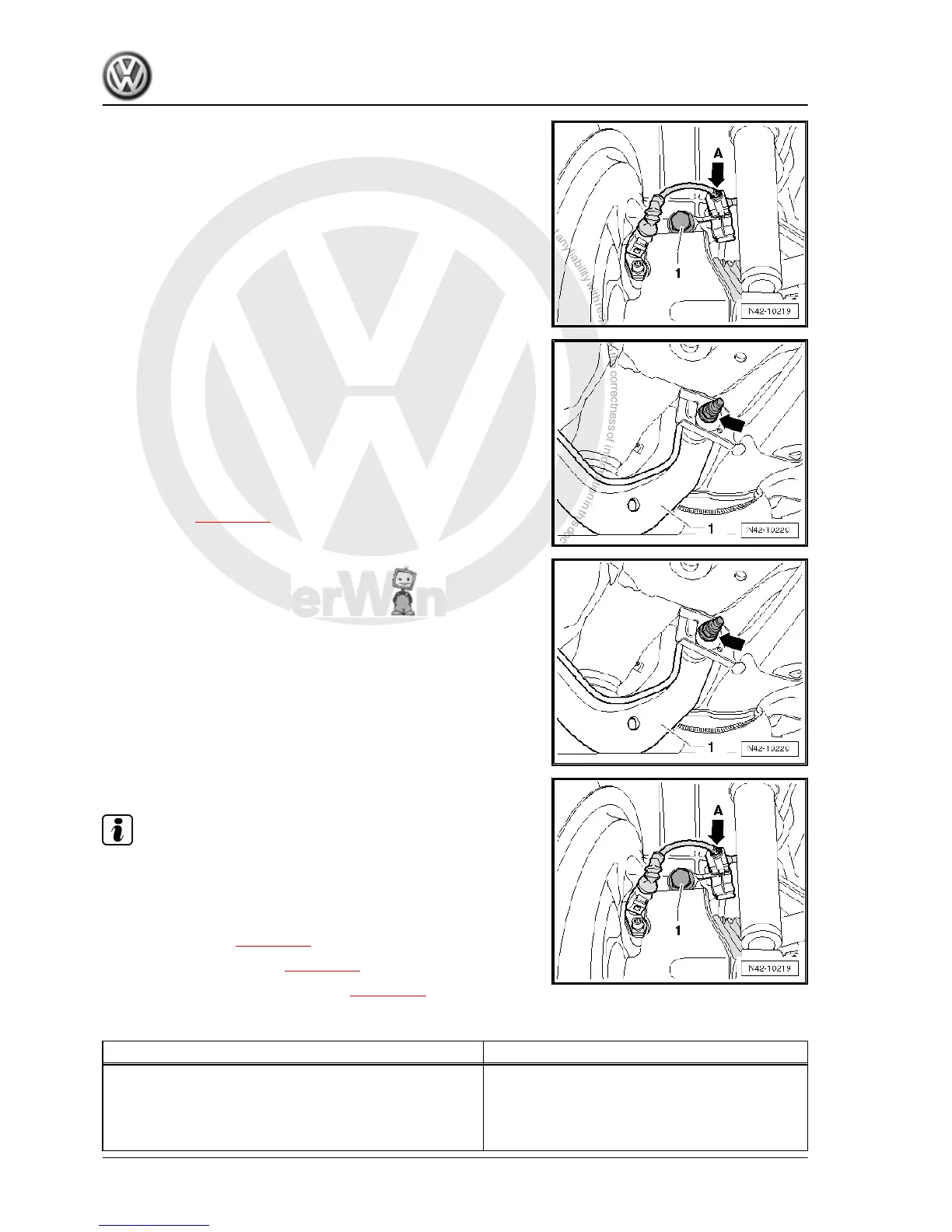
– Unhook speed sensor line -arrow A- from upper transverse
link.
– Remove bolt -1-.
– Mark position of eccentric bolt -arrow- relative to subframe us‐
ing e.g. a felt tip pen.
– Remove bolt -arrow-.
– Remove upper transverse link -1-.
Installing
– Install upper transverse link on vehicle and tighten bolts hand
tight.
The transverse link may only be bolted when dimension“a” has
been attained ⇒ page 188 .
– Bolt upper transverse link -1- to subframe and tighten new nut
-arrow-.
– Observe mark made for position of eccentric bolt -arrow- rel‐
ative to subframe.
– Tighten bolt -1- for upper transverse link.
Note
Ensure that a washer is installed between the bolt and the wheel
bearing housing.
– Attach speed sensor line -arrow A- from upper transverse link.
– Install coil spring ⇒ page 257 .
– Install wheel and tighten ⇒ page 288 .
– Check and adjust wheel alignment ⇒ page 305 .
Specified torques
Component Specified torque
Upper transverse link to wheel bearing housing
♦ Use new nuts and bolts
♦ Tighten threaded connections only when vehicle is in
the normal running position
130 Nm + 90° further
Golf 2004 ➤ , Golf Plus 2005 ➤
Running gear, axles, steering - Edition 08.2009
228 Rep. Gr.42 - Rear suspension

 Loading...