Group 30: Electrical system Component description
15
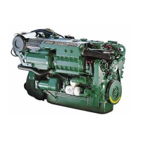
Sensor, boost pressure/ boost
temperature
The boost pressure and the boost temperature are
measured by a combined sensor located on the inlet
manifold on the left of the engine.
The sensor is supplied by a 5 Volt reference voltage
from the engine control module.
The boost pressure sensor measures the absolute
pressure, which is the sum of the boost pressure and
atmospheric pressure (300 kPa thus corresponds to a
boost pressure of 200 kPa when atmospheric pres-
sure is 100 kPa).
The pressure signal is a voltage signal which is pro-
portional to absolute pressure.
The boost temperature sensor consists of a non-lin-
ear resistor, whose resistance varies with boost tem-
perature. The resistance falls as the temperature ris-
es.
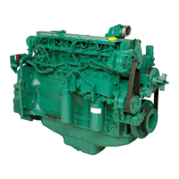
Sensor, oil pressure, engine
Oil pressure is measured by a sensor installed in the
engine block on the right side of the engine.
The sensor measures pressure in the main oil gallery,
and is supplied by a 5 Volt reference voltage from the
engine control module.
The pressure signal is a voltage signal which is pro-
portional to the lubrication oil pressure.
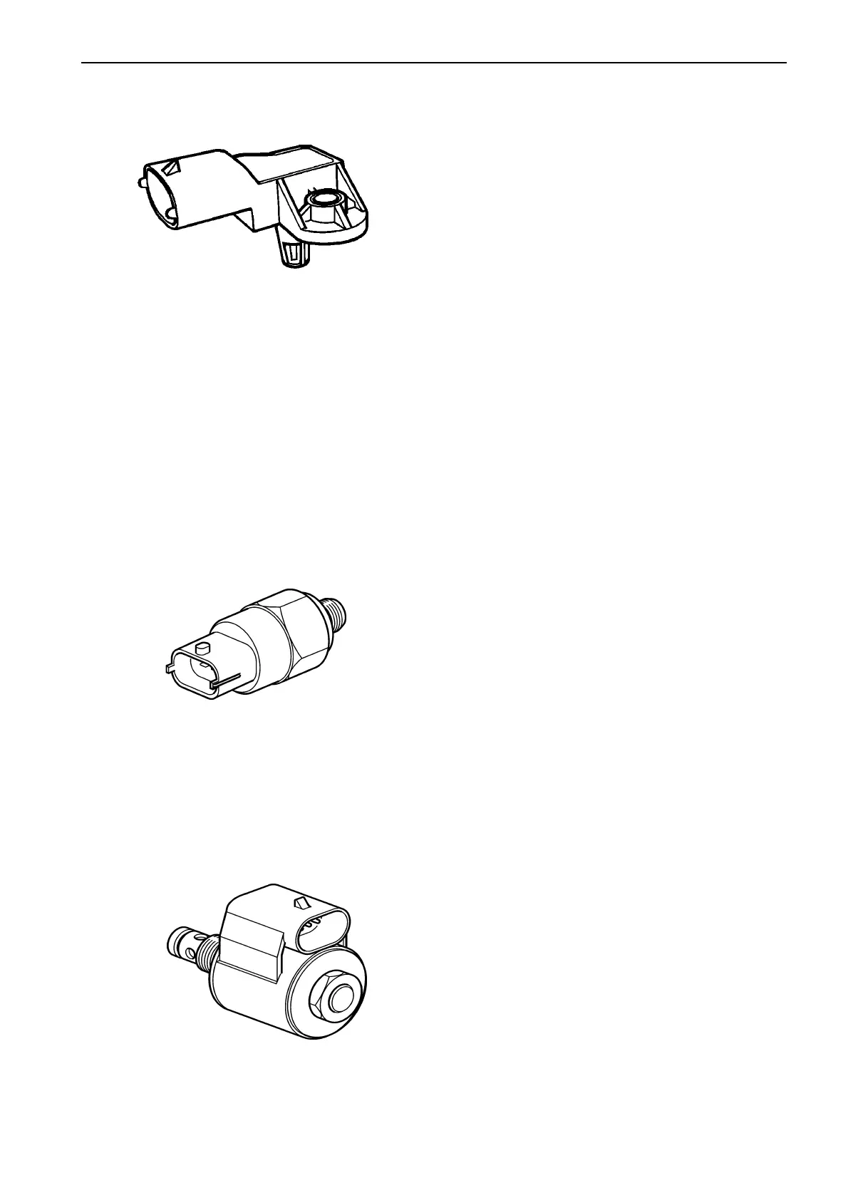
IEGR (only VE engines)
The IEGR valve is a 2-way solenoid valve controlled by
the engine control unit. The IEGR solenoid controls a
oil pressure that effects a control valve which activate
the exhaust gas recirculation function.
 Loading...