Group 30: Electrical system Diagnostic Trouble Codes
37
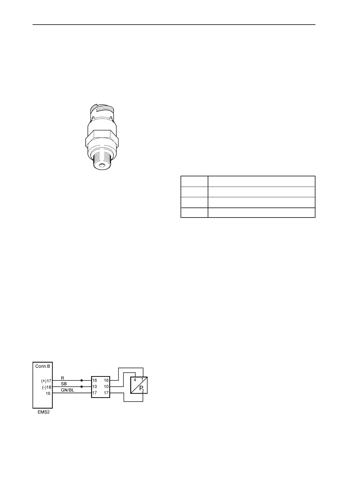
Circuit description
The sensor is an active sensor, i.e. the sensor must
receive operating voltage. Pin B17 on the engine con-
trol unit provides pin 1 on the sensor with an operating
voltage of +5 Volt. Pin 4 on the sensor is connected to
battery negative via pin B18 on the engine control unit.
The output signal from the pressure sensor, pin 2 on
the sensor to pin B16 on the EMS 2, is a voltage sig-
nal that is proportional to the fuel pressure.
MID 128, PID 94
Fuel pressure
MID 128: Engine control unit
FMI 1: The sensor value is valid but below the nor-
mal working range.
FMI 3: The voltage exceeds the normal value or is
short circuited to higher voltage.
FMI 5: The current is less than the normal value or
is open circuited.
FMI 7: Mechanical fault. The system responds in-
correctly.
FMI Fault code explanation
1 Fuel pressure is too low
3, 5 Faulty sensor / Faulty sensor circuit
7 Fuel pressure is critically low
Fault indication
DCU: Engine warning in DCU display.
CIU: Flash code
Flash code
Electrical fault: 3.6
Value fault: 3.8
Symptom
None
splice
splice
fuel pres-
sure
engine
interface
Note! Only TAD 650, 660, 750, 760 has an engine interface. On
TAD 734 the wiring to the EMS 2 is the same but without any en-
gine interface.
 Loading...