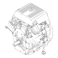
Reassembly Procedures WM 90 Repair
wc_tx000389gb.fm 66
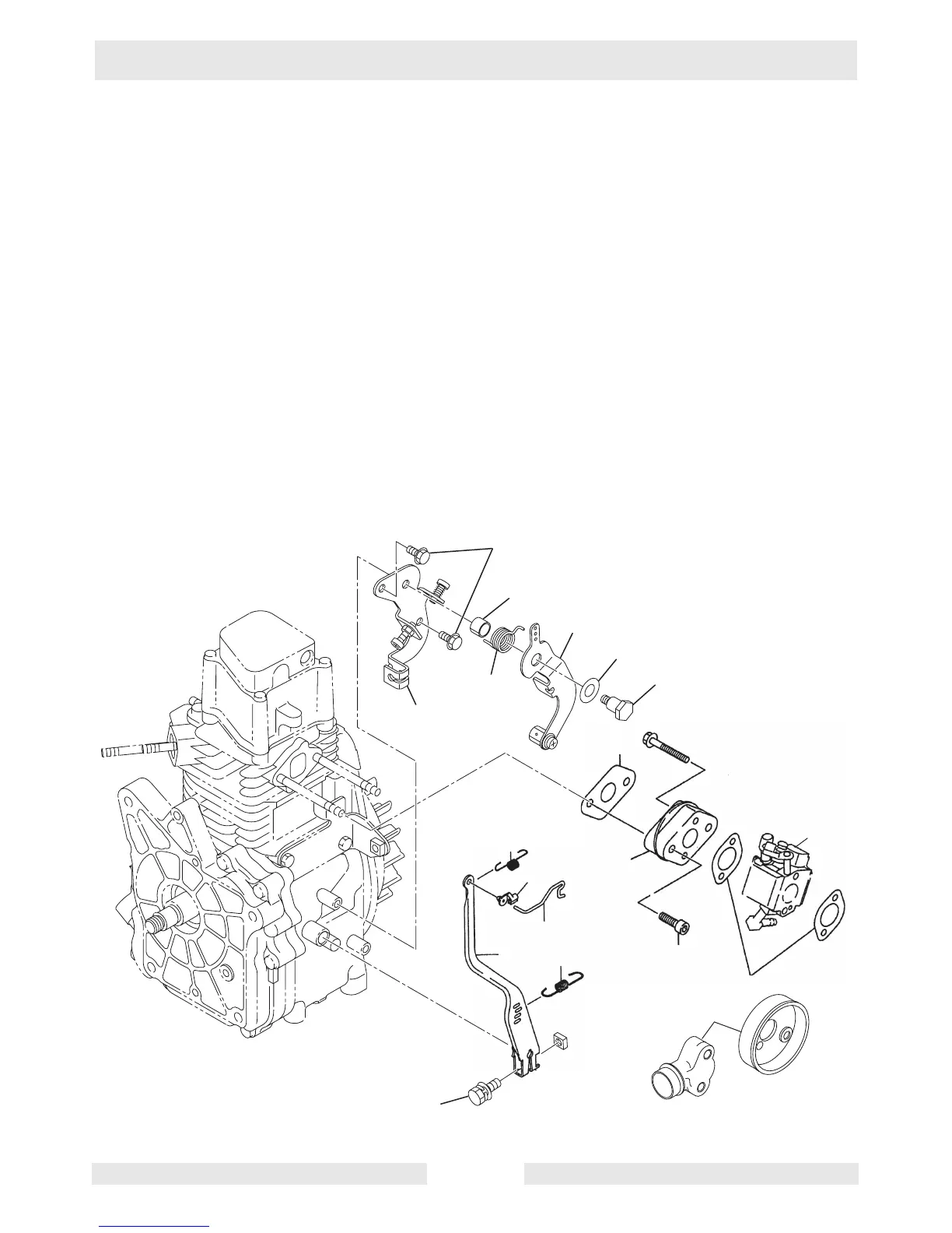
8.15 Installing Governor, Speed Control System, and Carburetor
See Graphic: wc_gr001890
8.15.1 Install governor lever (a) to governor shaft, then tighten the locking bolt
(b) temporarily.
8.15.2 Install baseplate (t) to crankcase using two M6 x 8 flange bolts (s).
8.15.3 Install the speed control lever (p), friction washer (o), pivot bolt (n),
spacer (r) and return spring (q).
8.15.4 Attach the governor spring (c) to proper holes (as marked during
disassembly) of governor lever and speed control lever.
8.15.5 Using bolts (j), install insulator (k) and gasket (m).
8.15.6 Install carburetor (i) and gaskets (h) to cylinder head. Also install
appropriate carburetor flange (g).
8.15.7 Install bushing (f). Install governor rod (d) to governor lever and throttle
lever of carburetor. Attach spring (e) over governor rod.
8.15.8 See section Adjusting Governor System.
a
b
c
d
e
f
g
h
i
j
k
p
o
q
t
s
r
n
wc_gr001890
m
 Loading...