83
EPG-SPRINT / EPG-SPRINT X
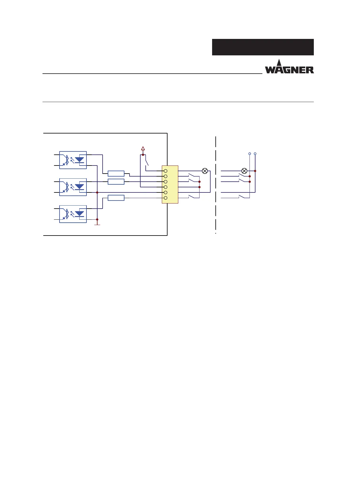
P_01356
Pin
1
2
3
4
5
6
24VDC
GND
R1
6.6k
R2
6.6k
R3
6.6k
GND
GND
24VDC
EPG-Sprint / X
SERVICE MANUAL
VERSION 09/2017 ORDER NUMBER DOC2309350
12 EXTENDED INTERFACE FOR REMOTE CONTROL
The "Remote Control" interface changes the assignments of the signals depending on the
operating mode.
The "Remote Control" connection allows the EPG to be switched on/o , faults to be displayed,
a fault to be reset and 50 recipes to be selected.
Hardware interface/signal description:
Pin 1 = fault output 24 VDC/300 mA maximum
Pin 2 = fault reset input 24 VDC/3.3 mA
Pin 3 = input ON/OFF 24 VDC/3.3 mA
Pin 4 = output 24 VDC/300 mA maximum
Pin 5 = GND reference mass for signals
Pin 6 = recipe selection input 24 VDC/3.3 mA
12.1 MANUAL GUN MODE
Control of valve for vibrator
Hardware interface/signal description:
Pin 1 = vibrator control output 24 VDC/300 mA maximum
Pin 3 = vibrator input and uidization on/o *
Pin 4 = 24 VDC/300 mA maximum*
Pin 5 = GND reference mass for output
* Pin 3 and Pin 4 enabled starting from software version D212
12.2 AUTOMATIC GUN MODE
6-pin plug order No. 9952951 or 2302240
Interface with
external supply
Interface with
internal supply
 Loading...