PREPARE INSTALLATION SITE
GENERAL INFORMATION
When installing the appliance and/or burner, be sure to
provide adequate space for easy service and maintenance.
Prior to installation of the oil burner, the heating system
should be carefully inspected for defects and cleanliness.
The flue passages and heat absorbing surfaces must be
clean to ensure maximum heat transfer. Soot acts as an
insulator, which retards the transfer of heat.
The combustion chamber, flue gas passages, and all doors
and openings must be tightly sealed to eliminate air
infiltration. Excess air decreases CO
2
levels and thus
lowers efficiency. Inspect the flue and chimney for leaks
and obstructions.
Be sure the chimney is of adequate size and height. Install
a draft regulator the same size as the flue pipe (see page 3
under Chimneys and Draft Regulators).
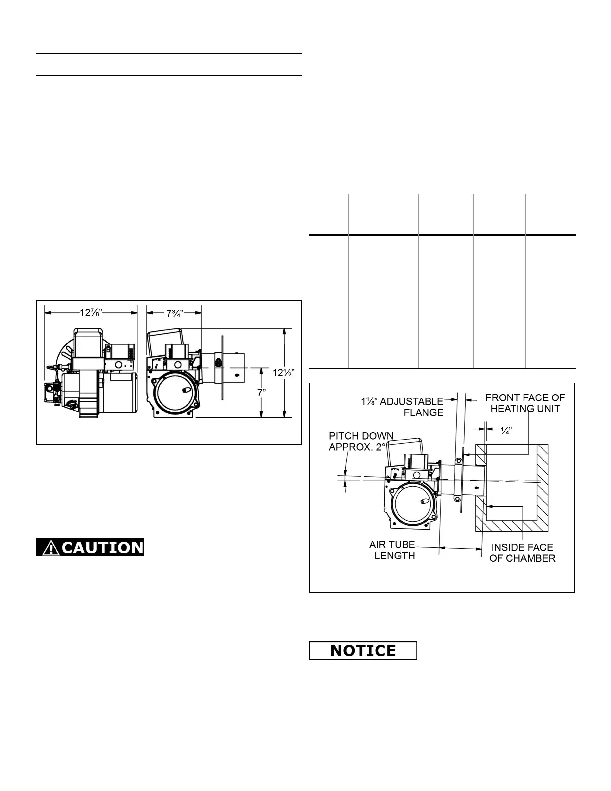
Figure 1: Overall Burner Dimensions
COMBUSTION CHAMBER
The purpose of a combustion chamber is to maintain a high
flame temperature by reflecting the heat back into the flame.
A high temperature ensures greater combustion efficiency
and lower stack losses. An insulating refractory or a Fiber
Fax type chamber can be used with this burner.
Caution should be taken when
installing Flamelock™ burners in
stainless steel combustion chambers, because of the higher
temperature levels produced by high performance flame
retention burners. The temperature may exceed the
temperature ratings of the stainless steel chamber and can
result in chamber burnouts.
It is important to select and install, if necessary, the correct
size chamber on a conversion job. (Suggested chamber
dimensions are shown in Table 1.) On the Flamelock™
conversion burners, the atomized oil burns just off the
Flamelock™ cone. On all oil burners, the atomized oil must
not touch the sides or bottom of chamber, or smoke will
result (see Figure 21, page 13). Install the burner so the
face of the air cone of burner is set 1/4” behind the inside
face of the chamber (See Figure 2).
To eliminate the smoke, excess air will be required, resulting
in high stack temperature and lower combustion efficiency.
When you are replacing a standard burner with a flame
retention burner, take the following precautions:
1. Use pliable ceramic liner to line the inside of chamber.
2. Adjust burner (see “Final Adjustments” on page 7).
Table 1: Suggested Combustion Chamber
Dimensions
Conversion or Upgrading
Chamber Dimensions (in inches)
Firing
Rate
(GPH)
Square
Chamber
Diameter
Round
Chamber
Height
Nozzle to
Floor
0.50 7 x 7 8 11 5 – 6
0.75 8 x 8 9 12 5 – 6
0.85 8½ x 8½ 9 12 5 – 6
1.00 9 x 9 10⅛ 12½ 5 – 6
1.25 10 x 10 11¼ 12½ 5 – 6
1.35 10½ x 10½ 11¾ 12¾ 5 – 6
1.50 11 x 11 12⅜ 13 5 – 6
1.65 11½ x 11½ 13 13¾ 5 – 6
2.00 12⅝ x 12⅝ 14¼ 13¾ 6 – 7
2.50 14¼ x 14¼ 16 14 7 – 8
3.00 15½ x 15½ 17½ 15 7 – 8
The “Air Tube Length” is the distance from the front of the
aluminum fan housing to the face of the Air Cone.
The maximum insertion depth of
any given air tube is reduced by
the thickness of the adjustable flange. Example: A 6” air
tube can only be inserted about 5”.
2
Figure 2: Combustion Chamber Detail
 Loading...