CALIBRATE AIR CONE POSITION
If any components have been replaced on a given gun
assembly, it may be necessary to calibrate the air cone
position. As long as the stop bracket is not loosened or
removed, this procedure is not necessary during normal
maintenance.
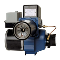
1. Loosen the stop bracket, pull it back to the zero
position, and re-tighten the bracket as indicated in
Figure 8.
Figure 8: Stop Bracket
2. Loosen the gun adjustment screw, slide the gun
assembly back until it is flat against the stop bracket,
and re-tighten the adjustment screw.
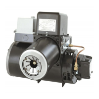
3. At this point, the Flamelock™ cone should be flush
with the stepped face of the air cone (See Figure 13,
page 7). If it is not flush, loosen the 3 screws
securing the air cone in place.
Figure 9: Air Cone Mounting Screws
4. Adjust the air cone to be flush with the Flamelock™
cone and tighten the 3 air cone screws.
5. After completing this calibration, it will be necessary to
re-tune burner and check combustion.
WIRING
All wiring must comply with the National Electric Code and
local ordinances. Refer to diagram supplied with burner or
controls, making sure the burner and controls are wired
correctly and that the line switch is properly connected to a
20 amp fused service.
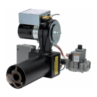
To use with line voltage
thermostat, jumper terminals T-T
and add thermostat as shown at (1) in series with limit
control.
Figure 10: Intermittent Ignition Wiring
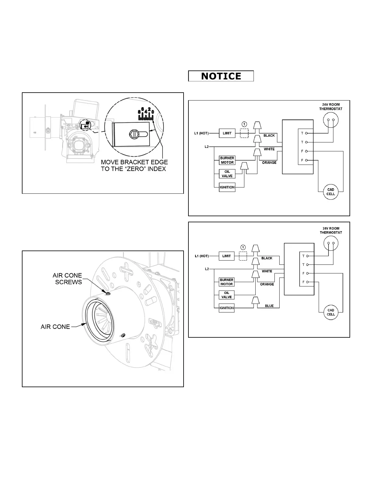
Figure 11: Interrupted Ignition Wiring
6
 Loading...