www.webasto.us 23 Webasto Product N.A., Inc.
DBW 2010/2020/300 COOLANT HEATERS TROUBLESHOOTING
5. TROUBLESHOOTING
5.2 TESTER INSTRUCTIONS
(TESTER P/N 1302691A)
The tester unit has been designed to quickly check the
proper operation of the various heater components. By
using the tester in place of the heater control unit, you
are able to manually control the heater to test
components and actually operate the unit in heating
mode.
The actual testing is completed in two steps, first you
perform an individual component test and then a manual
start and run test, both designed to pinpoint actual
problems in the heater system.
The tester should be used in conjunction with this Service
and Repair Manual (P/N 699745) which details complete
troubleshooting and repair procedures.
5.2.1 TEST PROCEDURES
SETUP:
A. Remove connector blocks from heater control unit,
inspect for loose wires, corrosion and proper wire
connections.
B. Plug control unit connector blocks into tester.
C. Set heater switch/timer to “ON” and turn vehicle
heater valve to “FULL” mode (if equipped).
D. Proceed to component test procedures.
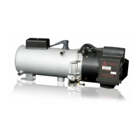
5.1 QUICK CHECK TROUBLESHOOTING MATRIX
PROBLEM
Switch On No Function
Control Light OFF after 30 Seconds
Blower Motor in Unit Inoperative
Blower Motor in Unit No Prime Cycle
Blower Motor in Unit No After-run
Coolant Circulating Pump Inoperative
Ignition Spark Absent
Combustion Does Not Take Place
Combustion Stops After 30 Seconds
Combustion Cannot Be Stopped
During Combustion Light Color Smoke
During Combustion Dark Color Smoke
Heating Unit Overheating
Electrical Fuse
Electrical Harn
ess
and Connections
Inertia Switch (Scho
lastic Heater Only)
ON / OFF Switch or Wiring
OverheatFuse(WhiteWires)
Temperature Limiter (Green Wires)
Control Thermosta
t (Green and R
ed Wires)
Flame Detector (Photo-cell)
Control Unit
Ignition Electrodes
Ignition Coil – Coil Wires
Electric Motor
Fuel Sup
ply
Fuel Pump
Fuel Solenoid Valve
High Pressure Nozzle
Coo
la
nt Circula
ting Pump
CombustionAi
rIntake
Exhaust System
Heating System
Voltage Supply
CHECK, REPAIR OR REPLACE AS NECESSARY
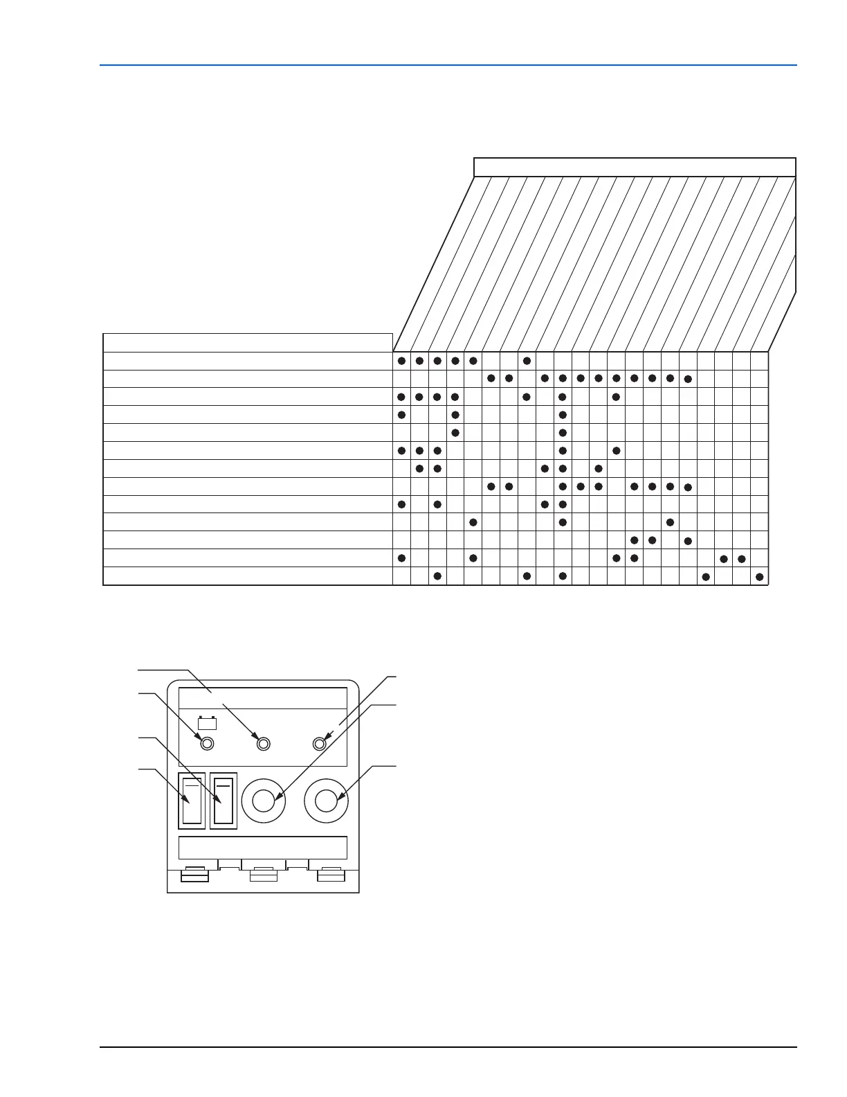
TESTER 440280 for DBW 2010/2020/300 in 12 or 24 Volt
Appareil de Contrôle 440280 pour DBW 2010/2020/300 in 12 or 24 Volt
+–
On
(Ouvert)
On
(Ouvert)
Control
Thermostat
(Aquastat)
Flame
Control
(Cellule
photoélectrique)
Water Pump
(Pompe de
circulation)
Motor
(moteur)
Ignition Coil
(Centrale
d'allumage)
Solenoid Valve
(Aimant
d’électrovanne)
1
2
5
4
3
6
7
1 LED – input power to heater
2 LED – control thermostat
3 LED – flame detector
4 On/Off switch – water pump
5 On/Off switch – motor
6 Push Button – ignition spark coil
7 Push Button – fuel solenoid valve
 Loading...


