Webasto Product N.A., Inc. 46 www.techwebasto.com
SERVICING DBW 2010/2020/300 COOLANT HEATERS
The combustion air inlet must be located so that no
exhaust fumes can enter.
If the heater is located near the fuel tank in a common
installation compartment, combustion air must be taken
in from and the exhaust routed to the exterior. The feed-
through holes must be sealed against splash water.
If the heater is located in a closed installation box, a vent
port is required:
• DBW 2010: 20 cm
2
(3.1 inch
2
)
• DBW 2020/300: 30 cm
2
(4.65 inch
2
)
If the temperature in the installation box exceeds the
permitted ambient temperature of the heater (see
Technical Data), the vent port must be enlarged.
8.6.4 EXHAUST LINE
CAUTION: Observe official regulations
concerning the installation (see 1.6).
The exhaust pipe outlet opening must not point in the
direction of motion.
The exhaust pipe outlet opening must be located so as
not to expect clogging by snow or mud.
The combustion air intake and exhaust outlet is to be
located so that no air pressure difference builds up in any
operating condition of the vehicle.
Rigid pipes made of unalloyed or alloyed steel with a
minimum wall thickness of 1.0 mm have to be used as
exhaust line or flexible pipes made of alloyed steel only.
The exhaust pipe is secured to the air heater e.g. with a
clamp.
– Permissible exhaust line dimensions:
DBW 2010 = 38 mm (1.5 in.)
DBW 2020 up to .32 / DBW 300 up to .15 = 80 mm
(3.15 in.)
DBW 2020 from .33 / DBW 300 from .165 = 70 mm
(2.75 in.)
– max. length: 5 m (16 ft)
– max. bend: 270°
As an alternative an exhaust deflector can be installed
when cleared by Webasto.
8.7 REMOVAL AND INSTALLATION
CAUTION: In installed condition only the
following disassembly or removal
procedures are permitted should enough
space for removal allow such action:
– replacement of temperature limiter
– replacement of temperature control thermostat
– replacement of overheat fuse
– replacement of burner
– replacement of fuel atomizing nozzle
– replacement of nozzle preheat cartridge
– replacement of nozzle preheat thermostat
– replacement of ignition coil
– replacement of flame detector
– replacement of combustion chamber
– replacement of control unit
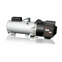
8.7.1 HEATER, REMOVAL AND INSTALLATION
8.7.1.1 REMOVAL
1. Disconnect connectors of cable harness in vehicle
and of circulation pump.
2. Disconnect combustion air intake on heater if
equipped.
3. Loosen clamp on exhaust outlet.
4. Loosen fuel supply and return line connections and
fit dummy plugs. Close water valves as applicable.
5. Loosen hose clamps on coolant hoses, disconnect
hoses and fit dummy plugs.
6. Remove 3 screws and washers or 4 screws and
washers of heater base.
7. Remove heater.
8.7.1.2 INSTALLATION
1. Locate heater for installation and secure with 3
screws and washers or 4 screws and washers.
2. Secure line on exhaust outlet using clamp.
3. Slide on coolant hoses and fasten with hose clamps.
Torque clamps with 1.5 Nm. Open water valves.
4. Connect fuel supply and return lines and tighten
connections or screw tight with banjo bolt and new
gaskets.
5. Secure combustion air inlet line on heater if
applicable.
6. Connect electrical connectors of cable harness in
vehicle and to circulation pump.
7. Bleed fuel supply system.
8. Bleed coolant circuit.
 Loading...


