www.webasto.us 53 Webasto Product N.A., Inc.
DBW 2010/2020/300 COOLANT HEATERS REPAIR
9.2.6 FUEL VALVE AND SOLENOID, REPLACEMENT
9.2.6.1 REMOVAL
1. Swing open or remove burner head (see Sec. 9.2.5).
2. Disconnect the ignition leads from the ignition
electrodes.
3. Loosen the retaining clamp bolt and dismount the
ignition electrodes.
4. Remove disc retaining ring and disc. Allow the disc
to hang from the electrical leads.
5. Disconnect the electrical leads from the fuel
solenoid.
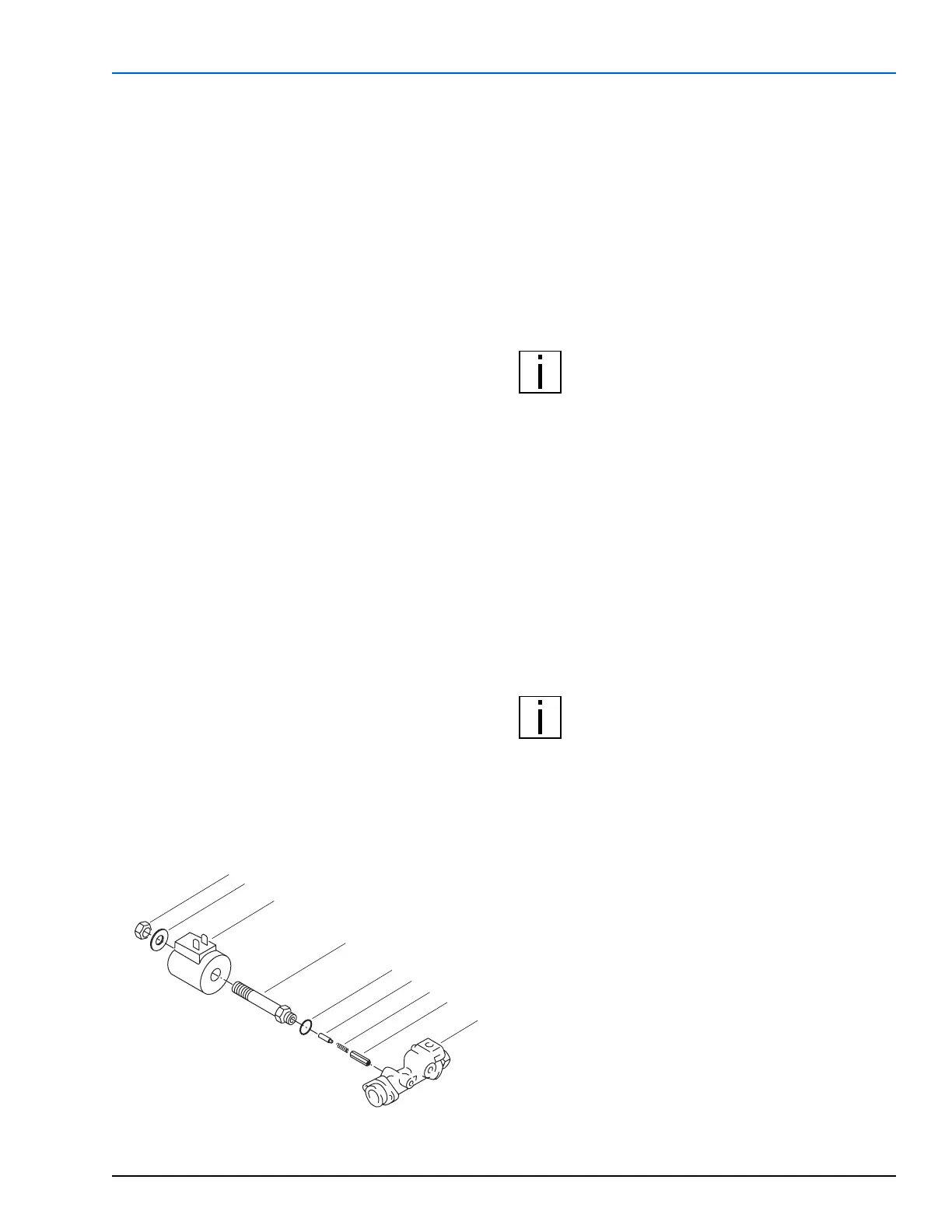
6. Unscrew the lock-nut (item 1, Fig. 39) securing the
solenoid to the valve chamber (4) and slide
magnetic head (3) back.
7. Unscrew valve chamber (4) from nozzle holder (9).
9.2.6.2 INSTALLATION
1. Unscrew lock-nut (item 1, Fig. 39) from new valve
assembly.
2. Make sure new O-ring seal (5) is in place on valve
chamber (4) and items 6, 7 and 8 are present and
correctly oriented inside the valve chamber.
3. Screw assembled valve into nozzle holder and
torque to 11.5 Nm (8.5 lb-ft).
4. Slide the magnetic head (3) into place making sure
the boss registers in the end plate recess.
5. Secure with the lock-nut (1) and washer (2).
6. Install the round disc and retaining ring.
7. Connect electrical leads to fuel solenoid.
8. Install and adjust ignition electrodes (see Sec. 6.2.3).
9. Install burner head (see Sec. 9.2.5).
Figure 39: Fuel Valve and Solenoid Assembly
9.2.7 FUEL PUMP, REPLACEMENT
9.2.7.1 REMOVAL
1. Remove burner head (see Sec. 9.2.5).
2. Disconnect electrical leads from solenoid valve,
flame detector, nozzle pre-heater and ignition
electrodes.
3. Loosen the retaining clamp bolt and dismount the
ignition electrodes.
4. Remove disc retaining ring and disc.
NOTE: During the following steps, ensure that
escaping fuel is captured or immediately
neutralized and properly disposed of.
5. Disconnect the fuel return and supply pipes from
the fuel pump.
6. Disconnect the fuel delivery pipe from the pump to
the nozzle holder.
7. Unscrew the four screws on the back wall and take
the complete assembly out.
8. Remove the retaining ring from the fuel pump shaft
and dismount the gear-wheel.
9. Remove the two bolts securing the fuel pump to the
back wall.
9.2.7.2 INSTALLATION
NOTE: Do not disturb the pump pressure
regulating screw. The pump has been pre-set to
the correct pressure.
1. Attach new fuel pump to back wall with the two
screws removed earlier.
2. Install gear-wheel on pump shaft and secure with
retaining ring.
3. Dot gear-wheel in four places with ISOFLEX LDS 18
Special A lubricant P/N 143820 (45 gram tube).
4. Insert assembly into burner head being careful to
mesh gears and secure with the four bolts removed
earlier.
5. Connect fuel pipes.
6. Install disc with flame detector and retain with ring.
7. Install and adjust ignition electrodes (see Sec. 6.2.3).
8. Install burner head (see Sec. 9.2.5).
1
2
3
4
5
6
7
8
9
1 Lock-nut
2 Washer
3 Magnetic Head
4 Valve Chamber
5 O-ring
6 Stepped Roll Pin
7 Spring
8 Plunger
9 Nozzle Holder
 Loading...


