Webasto Product N.A., Inc. 42 www.techwebasto.com
CIRCUIT DIAGRAMS DBW 2010/2020/300 COOLANT HEATERS
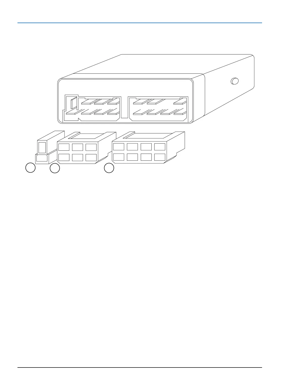
7.8 CONTROL UNIT - IDENTIFICATION OF TERMINALS
1
23
4
5
6
1
2
1
2
4
56
7
8
A
C
B
CONNECTOR BLOCK A
A1 (–) coolant circulating pump
A2 (+) coolant circulating pump
C
ONNECTOR BLOCK B
B1 (+) On/Off switch with low voltage protection
B2 (–) Battery negative
B3 (+) Control light (Operation indicator)
B4 (+) Battery positive
B5 (+) Optional coolant pump control input
B6 (–) Control light (Operation indicator)
C
ONNECTOR BLOCK C
C1 (+) To temperature control thermostat*
C2 (+) To Blower motor
C4 (+) To overheat fuse, temperature limiter and
fuel solenoid valve
C5 (–) For all heater components
C6 (–) Flame detector
C7 (+) From normally closed control thermostat
C8 (+) To ignition coil
* Control thermostat with white and orange wires.
Closes at 60 ± 5° C (140 ± 9° F)
Opens at 70 ± 3° C (158 ± 6° F)
* Control thermostat with red and green wires.
Closes at 68 ± 5° C (154 ± 9° F)
Opens at 75 ± 3° C (167 ± 6° F)
Figure 33: Control Unit - Identification of Terminals
 Loading...


