Webasto Product N.A., Inc. 32 www.techwebasto.com
FUNCTIONAL ADJUSTMENTS DBW 2010/2020/300 COOLANT HEATERS
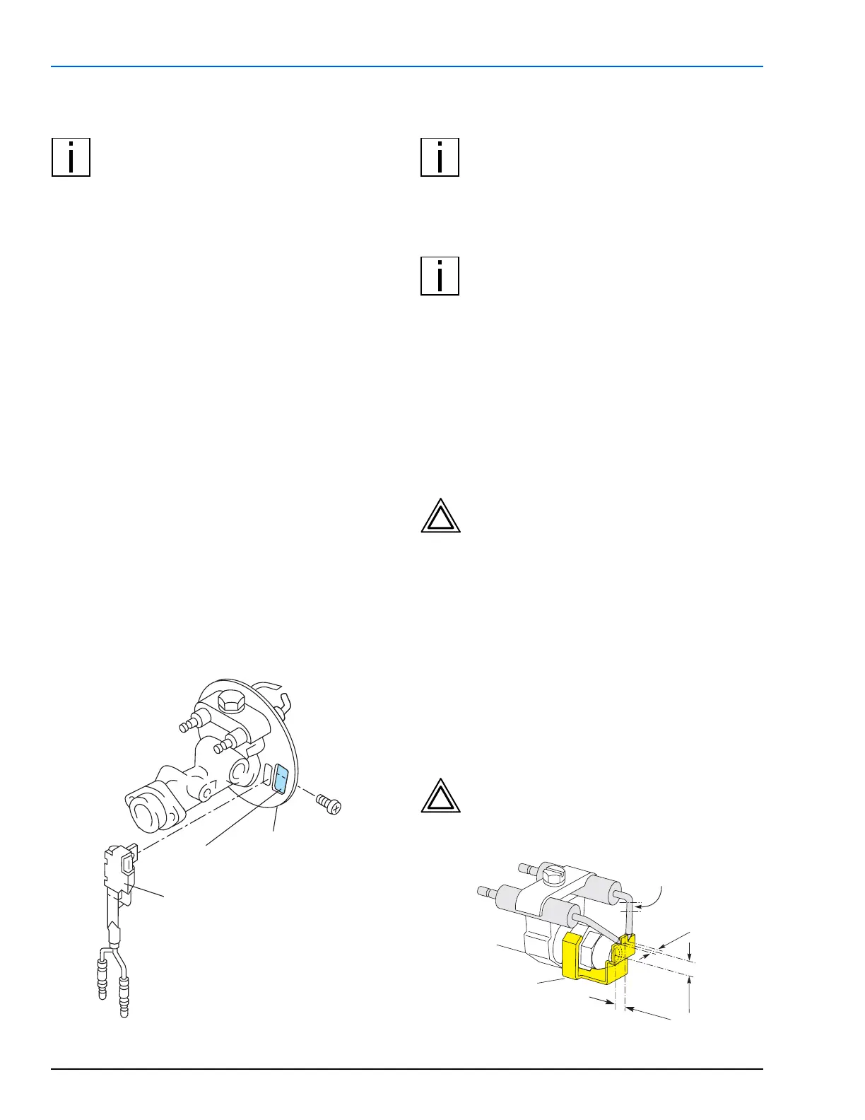
6.2.2 FLAME DETECTOR RESISTANCE CHECK
NOTE: The glass bulb of the flame detector
and the viewing glass of the window (refer to
Fig. 22) are to be cleaned if contaminated.
In case of damage, cracked glass bulb or not obtaining
the rated values, replace the flame detector.
C
HECK
– Swing burner head open (see Sec. 8.5.1)
– Disconnect flame detector leads
– Connect flame detector leads to ohm meter
– Cover flame detector glass bulb with your thumb
– Check resistance (rated value: < 20 kOhm)
– Uncover flame detector and expose to strong light
– Check resistance (rated value: < 200 Ohm)
A
LTERNATE METHOD USING TESTER (P/N 1302691A)
– Exchange control unit with tester and swing burner
head open (see Sec. 8.5.1).
– Watch “Flame Control” LED while holding your
thumb over the flame detector glass bulb. LED will
darken considerably.
– Remove your thumb, LED will brighten considerably.
(Shine a bright light on the flame detector if in a
dimly lit area.)
– The fluctuation of the LED between dim and bright
will indicate the flame detector is working properly.
Figure 22: Flame Detector Check
6.2.3 IGNITION ELECTRODE CHECK AND SETTING
NOTE: The insulation body of the ignition
electrodes must not show any damage.
Damaged insulation of the electrodes requires
their replacement. Setting ignition electrodes
with a spacing beyond the tolerances shown in
Fig. 23 may or will cause ignition failures.
NOTE: The ignition electrodes can be set with
the setting gauge as shown. In addition the
front edge of the setting gauge must rest
against the atomizer nozzle and the tips of the
electrodes in both notches.
C
HECK
– Swing burner head open (see Sec. 8.5.1)
– Insulation body of the ignition electrodes for
damages
– Electrode spacing with setting gauge according to
Fig. 23.
CAUTION: Do not touch the nozzle drilling
while measuring the electrode spacing.
Keep the electrode setting gauge clean and
free of contaminates.
S
ETTING
– Place setting gauge over nozzle as shown.
– Loosen clamp bolt until electrode can be moved with
slight effort
– If necessary, electrodes can be bent slightly to
conform to the setting gauge notches. Grip with
pliers at the bending point only.
– Once set, snug up clamp bolt and check electrode
spacing once again to confirm setting.
CAUTION: Do not over-tighten or bottom
out clamp bolt. Doing so will distort the
clamp causing the electrodes to spread
apart.
Figure 23: Setting of Ignition Electrodes
Flame Detector
Window
Screw
Disc
5 ±
0.5
8 ±
0.5
4.5 ±
0.5
If necessary,
grip here to bend
Millimeters
Setting Gauge
P/N 310646
 Loading...


