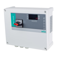
InstallationandoperatinginstructionsWilo-EasyControlMS-L1x4kW 31
INSTALLATION English
tobexedsecurelyandfunctionally.Theoperator
or the supplier is responsible for the provision of
the foundations and their suitability in terms of
dimensions, stability and strength.
• The following ambient conditions must be ob-
served.
• Ambient/operatingtemperature-30...+60°C
• Max.relativehumidity:50%
• Overow-proofassembly
• Check the available planning documentation
(installation plans, design of installation location,
wiring diagram) is complete and correct.
• Please also observe the applicable national acci-
dent prevention regulations and trade association
safety provisions.
5.3.1. Basic advice on xing the switchgear
The switchgear can be installed on various
structures (concrete wall, mounting rail etc.). For
thisreason,thexationmaterialsprovidedby
the customer must be suitable for the relevant
structure.
Observethefollowinginstructionsforthexation
material:
• Ensure the proper edge clearance in order to
prevent the construction material from tearing or
chipping.
• The size of the borehole depends on the size of
the bolts. The borehole should be 5 mm deeper
than the bolt length.
• Drilling dust impairs holding strength. Therefore
Always blow or vacuum out the borehole.
• Makesurethexationmaterialisnotdamaged
during assembly.
5.3.2. Assembling the switchgear
Wall-mounted installation
Fixtheswitchgeartothewallusing4screwsand
4 anchors.
1. Open the cover on the switchgear and place this
on the intended assembly area.
2. Draw the four holes on the assembly area.
• Drillingdistances(WxH):140x219mm
• Observe the information on the underside of
the switchgear too!
3. Drilltheholesaccordingtothespecicationsfor
thexationmaterialsused.
4. Fixtheswitchgearusingfourscrews(max.Ø:
4mm)andappropriateanchorsontothewall.
5.3.3. Positioning of signal transmitters
For automatic control of the connected pump,
a corresponding level control device must be
installed. This needs to be provided by the cus-
tomer.
Float switches may be used as signal transmitters.
Connection of level sensors or electrodes is not
possible! The corresponding signal transmit-
ters must be installed according to the system's
installation plan.
DANGER of explosions!
If the connected signal transmitters are
used in potentially explosive areas, there is a
danger of fatal injuries from explosions! The
connected signal transmitters must always be
used outside of potentially explosive areas.
Installation must always be carried out by a
qualied electrician.
Note the following:
• Whenusingoatswitches,ensurethatthesecan
move freely in the collector tank (sump, reservoir).
• The water level of the connected pump must not
fall below the minimum.
• Themaximumswitchingfrequencyofthecon-
nectedpumpmustnotbeexceeded.
5.4. Electrical connection
POTENTIALLY fatal danger due to electrical
voltage
Incorrect electrical connections can cause fa-
tal electric shocks. Electrical connections may
only be made by a qualied electrician who is
approved by the local energy supplier, in ac-
cordance with locally applicable regulations.
DANGER of explosions!
If the connected pump and signal transmitter
are used in potentially explosive areas, there
is a danger of fatal injuries from explosions!
The connected pump and signal transmitter
must always be used outside of potentially
explosive areas. Installation must always be
carried out by a qualied electrician.
NOTE
• Depending on the system's impedance and the
connectedconsumers'max.no.ofconnections/
hour,voltageuctuationsorvoltagedropsmay
occur. Always have the electrical connections
carried out by an electrician authorized by the
local energy supplier.
• Observe the installation and operating in-
structions for the connected pump and signal
transmitters.
• The mains connection current and voltage must
be as stated on the rating plate.
• All-pole disconnecting, K-type circuit breakers
must be installed!
• Max.fuseprotectiononmainsside:16A
• On switchgears without a power supply separa-
tion device ("O" version: without main switch or
plug) this must be provided by the customer!
• It is recommended a residual-current-operated
protection switch (RCD, type A, sinus wave-form
current) be installed. Observe the local laws and
regulations on this too!
• Route the power supply cable in accordance with
the valid norms and regulations and according to
the wiring diagram.
• Ground the system (switchgear and all electric
consumers) in accordance with the regulations.

 Loading...