38 WILO SE 08/2013 Ed.04 DIN A4
English APPENDIX
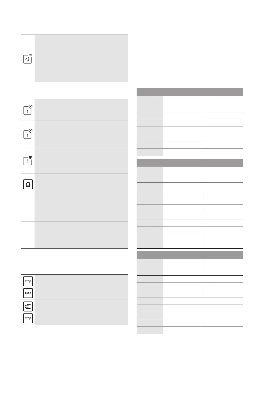
10.1. Acknowledging faults
After a fault occurs, a visual and audible warning is
output.
BybrieypressingtheBuzzerOFF/resetbutton,
the audible alarm is deactivated and collective fault
signal relay (SSM) acknowledged.
When held down for longer (min. 1 sec), the fault is
acknowledged and the control is reenabled.
A fault can only acknowledged once it has been
eliminated!
10.2. Fault signals
LED lights up red
Cause:permittedratedcurrenthasbeenexceeded,
excesscurrentreleasehasbeeninitiated
Solution: Check pump and setting of DIP switch
LED ashes red
Cause:Ratedcurrentbelow300mAduringopera-
tion or phase L2 missing
Solution: Check mains connection of switchgear
and pump connection
LED lights up red
Cause: Winding temperature monitoring has been
triggered
Solution: Check pump and wiring (converter bridge
may be missing); check pump operating conditions
LED lights up red
Cause: High-water alarm has been triggered.
Solution: Check pump/unit operating conditions
and level settings
All LEDs light up simultaneously for 2sec.
Cause: Button lock active
Solution: Deactivate the button lock by simulta-
neously pressing down the Manual Mode, Stop and
AutomaticModebuttons(forapprox.1s).
All LEDs light up from right to left.
Cause: Incorrect phase sequence in mains connec-
tion
Solution: Swap over 2 phases in the switchgear's
mains connection
10.3. Fault memory
The switchgear has a fault memory. The last fault
is stored retentively in the fault memory.
Opening the fault memory
By pressing down the Stop and Automatic Mode
buttons simultaneously, the last fault is indicated
by the corresponding LED.
Deleting the fault memory
The fault memory is deleted by simultaneously
pressingandholdingdown(forapprox.1s)the
Manual Mode and Stop buttons.
10.4. Further steps for troubleshooting
If the points listed here do not rectify the fault,
contact Wilo Customer Service. They can help you
as follows:
• Telephone or written support from Wilo Customer
Service
• On-site support from Wilo Customer Service
• Inspection or repair of the switchgear at the
factory
Please note that you may be charged for some
services provided by our Customer Service. For
more details, please contact Wilo Customer
Service.
11. Appendix
11.1. System impedance tables
System impedances for 1~230 V, 2-pole, direct starting
Power System impedance Connections/h
kW ohms
1.5 0.4180 6
2.2 0.2790 6
1.5 0.3020 24
2.2 0.1650 24
1.5 0.2720 30
2.2 0.1480 30
System impedances for 3~400 V, 2-pole, direct starting
Power System impedance Connections/h
kW ohms
2.2 0.2788 6
3.0 0.2000 6
4.0 0.1559 6
2.2 0.2126 24
3.0 0.1292 24
4.0 0.0889 24
2.2 0.1915 30
3.0 0.1164 30
4.0 0.0801 30
System impedances for 3~400 V, 4-pole, direct starting
Power System impedance Connections/h
kW ohms
3.0 0.2090 6
4.0 0.1480 6
2.2 0.2330 24
3.0 0.1380 24
4.0 0.0830 24
2.2 0.2100 30
3.0 0.1240 30
4.0 0.0740 30
11.2. Spare parts
Spare parts can be ordered from Wilo Customer
Service. To avoid queries and incorrect orders, the
serial and/or article number must always be stat-
ed. Subject to change without prior notice

 Loading...


