PRE-INSTALLATION
Greenstar i System Compact - 6 720 807 726 (2013/05)14
3.6.4 BATHROOMS
A boiler fitted with an FW100 controller may only be installed outside
the shaded area.
A boiler with any other timer fitted (or blanking panel) can also be
installed in zone 2.
Additional RCD (Residual Current Device) protection may be required.
Consult the latest version of BS7671 (IEE wiring regulations).
Fig. 13 Bathroom installations
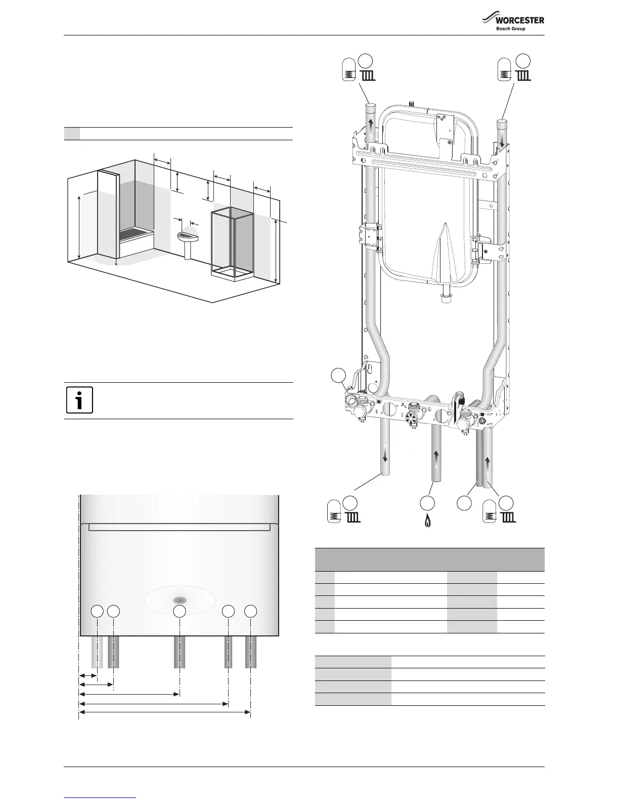
3.7 PLUMBING MANIFOLD
3.7.1 CONNECTIONS
• If the boiler pipes are to be run behind the appliance ensure that the
pipes pass either side of the expansion vessel as shown in figure 15.
• For further ease of fitting, an optional Vertical Pre-piping Assembly kit
is available, comprising three pre-formed copper pipes and a cross
bonding strip. Part number: 7 716 192 712.
• To cover the pipework under the boiler, down to the counter top, an
optional Worcester accessory “Below boiler pipe cover” can be used.
Part number: 7 716 192 608
Fig. 14 Pipe dimensions
Fig. 15 Plumbing manifold
Use the fittings supplied in the Hardware literature pack.
2* Without the end wall, zone 2 must extend 600mm from the bath
Further guidance on pipe routing can be found printed
on the boiler template (supplied with the boiler).
6720646608-124.2Wo
2*
Radius 600mm
Radius
600mm
2
1
2
2
2
1
2
2
2
1
600mm
600mm
600mm
750mm
2250mm
2250mm
2*
# Function
From left
case edge
Diameter of
pipe
1Condensate 33mm 22mm
2CH Flow 65mm 22mm
3Gas 195mm 22mm
4 Pressure Relief Valve 291mm 15mm
5CH Return 325mm 22mm
Table 5 Key to figures 14 & 15
Heating System 22mm compression fittings
Gas 22mm compression fittings
Condensate 22mm rubber push fit connector
PRV 15mm (fittings not supplied)
6720646609-06.2Wo
1
2 5
2 3 5
4
 Loading...