INSTALLATION
Greenstar i System Compact - 6 720 807 726 (2013/05) 27
4.7 ELECTRICAL
• The mains electrical supply to the boiler must be through either a
fused double pole isolator or a fused three pin plug and unswitched
socket, situated, where practicable, adjacent to the boiler.
• The isolator must have a contact separation of 3mm minimum in both
poles.
ACCESS TO ELECTRICAL CONNECTIONS:
▶ Access to all wiring connections are via the Installer access cover at
the bottom front of the control panel. No access is required to other
parts of the control board.
1.Refer to figure 46 and release the captive screws securing the
Installer access cover.
2.Remove the Installer access cover.
Fig. 46 Removing the installer access cover
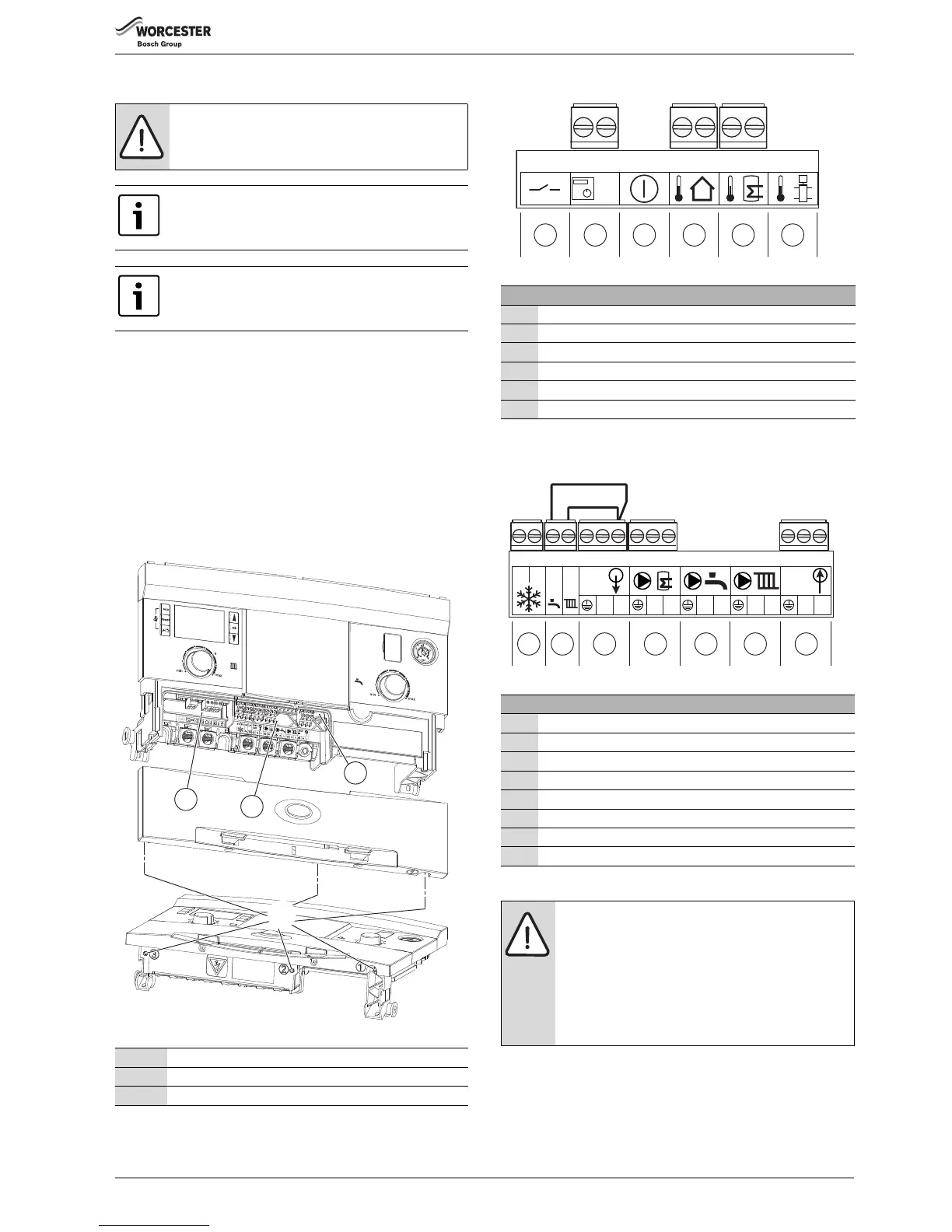
Low voltage connections
Fig. 47 Low voltage connectors
Mains voltage connections
Fig. 48 Mains voltage connectors
CAUTION: Isolate the mains electrical supply before
starting any work and observe all relevant safety
precautions.
Additional equipment requiring 230V must be
connected to the boiler‘s electrical supply.
The boiler is pre-fitted with a mains supply cable.
External fuse rating - 3 Amps
1 Low voltage connections
2 Mains voltage connections
3Fuse carrier - 5A
Low voltage terminal strip
1 Low voltage room thermostat input (Not used)
2EMS bus connections
3 External cut off switch (Not used)
4 Outdoor compensation sensor
5Cylinder sensor
6 Low Loss Header sensor (Not used)
Table 7 Key to figure 47
Mains voltage terminal strip
7 External frost thermostat
8 230 V A.C. switched live inputs
9 230 V A.C. mains output to wiring centre
10 Cylinder safety valve (G3)
11 DHW circulation pump (Not used)
12 Central heating circulation pump (Not used)
13 Boiler 230 V A.C. mains supply
* Pre-wired links
Table 8 Key to figure 48
NOTICE: DHW LR Input
▶ This connection also provides a 230V switched live
system input. Therefore both links must be removed
during system wiring.
▶ If the integral diverter valve kit is fitted, this
connection provides for the DHW channel if an
external 230V timer is used. If the timer is not fitted
the link must be in place to ensure a cylinder demand.
6720646609-45.1Wo
EMS
1 2 3 4
5
6
 Loading...