SERVICE AND SPARES
Greenstar i System Compact - 6 720 807 726 (2013/05)44
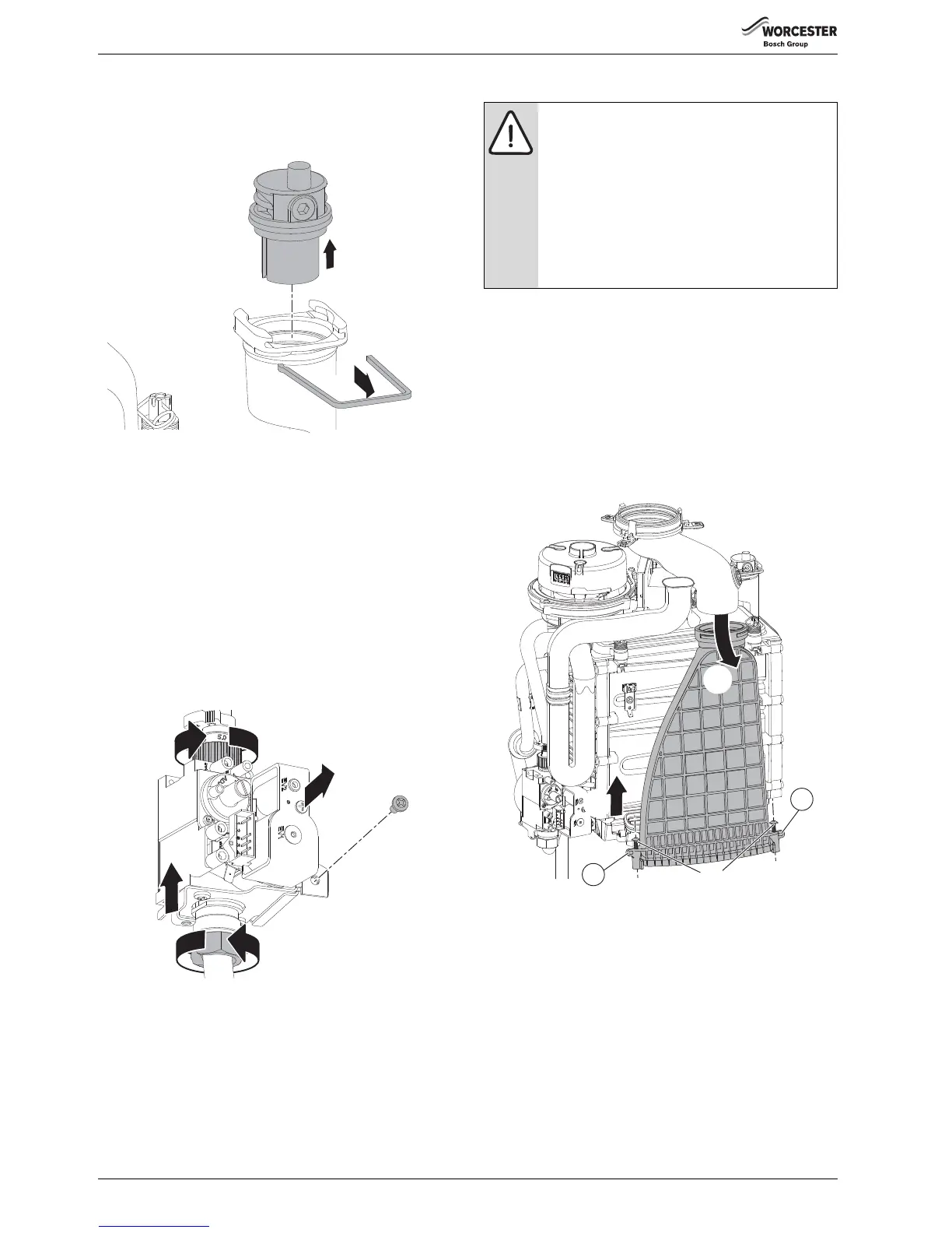
6.8.7 AUTO AIR VENT
Ensure that the boiler has been fully drained.
1.Remove the spring clip completely.
2.Lift the air vent out of the housing and remove.
Fig. 88 Auto air vent
When re-assembling ensure that the “O” ring is fitted to the Auto air vent
and NOT the heat exchanger, otherwise the Air vent will be difficult to fit.
Apply silicone grease to the “O” ring to ease assembly.
6.8.8 GAS VALVE
▶ Isolate the mains electrical supply and the gas supply at the boiler gas
cock.
▶ Remove the combustion air inlet pipe.
▶ Disconnect the electrical connector from the valve
1.Remove the gas pipe from the top of the valve.
2.Undo the bottom gas pipe connection.
3.Remove the screw securing the gas valve.
4.Lift the gas valve to clear the bottom gas connection.
5.Pull the gas valve forward out of the boiler.
Fig. 89 Gas valve
▶ When fitting the new valve, start with the bottom gas connection and
tighten by hand before making any other connections to the valve.
▶ Secure the valve with the screw.
▶ Tighten the bottom connection firmly with a suitable spanner.
▶ Connect the top gas pipe.
▶ Reconnect the electrical connector.
▶ Open the boiler gas isolator.
▶ Check all the gas connections for gas tightness.
6.8.9 FAN ASSEMBLY
To remove the fan, disconnect the electrical mains and gas supplies, and
remove the following components:
•Flueway
• Combustion air inlet pipe and gas pipe
FLUEWAY REMOVAL
▶ Refer to figure 90 for Flueway removal.
1. Release the two screws securing the Flueway to the sump.
2. Using a screwdriver under the tabs (1) next to the screws, lever the
Flueway up to clear the seal and pull the Flueway forward.
3. Rotate the exhaust pipe to the left and pull the Flueway down to
separate from the exhaust pipe.
Fig. 90 Flueway removal
CAUTION: Component replacement:
▶ After replacement of a gas related component, where
a gasket or seal has been disturbed or replaced, check
for gas tightness using a gas sniffer/analyser.
▶ On re-assembly check all affected seals for cracks,
hardness and deterioration.
If damaged or in any doubt the seal must be replaced.
▶Also after re-assembly, carry out the following
checks:
Fan pressure in section 6.5,
Flue gas analysis in section 6.6,
 Loading...