11
INSTALLATION & COMMISSIONING
8 716 115 752 (2009/07)
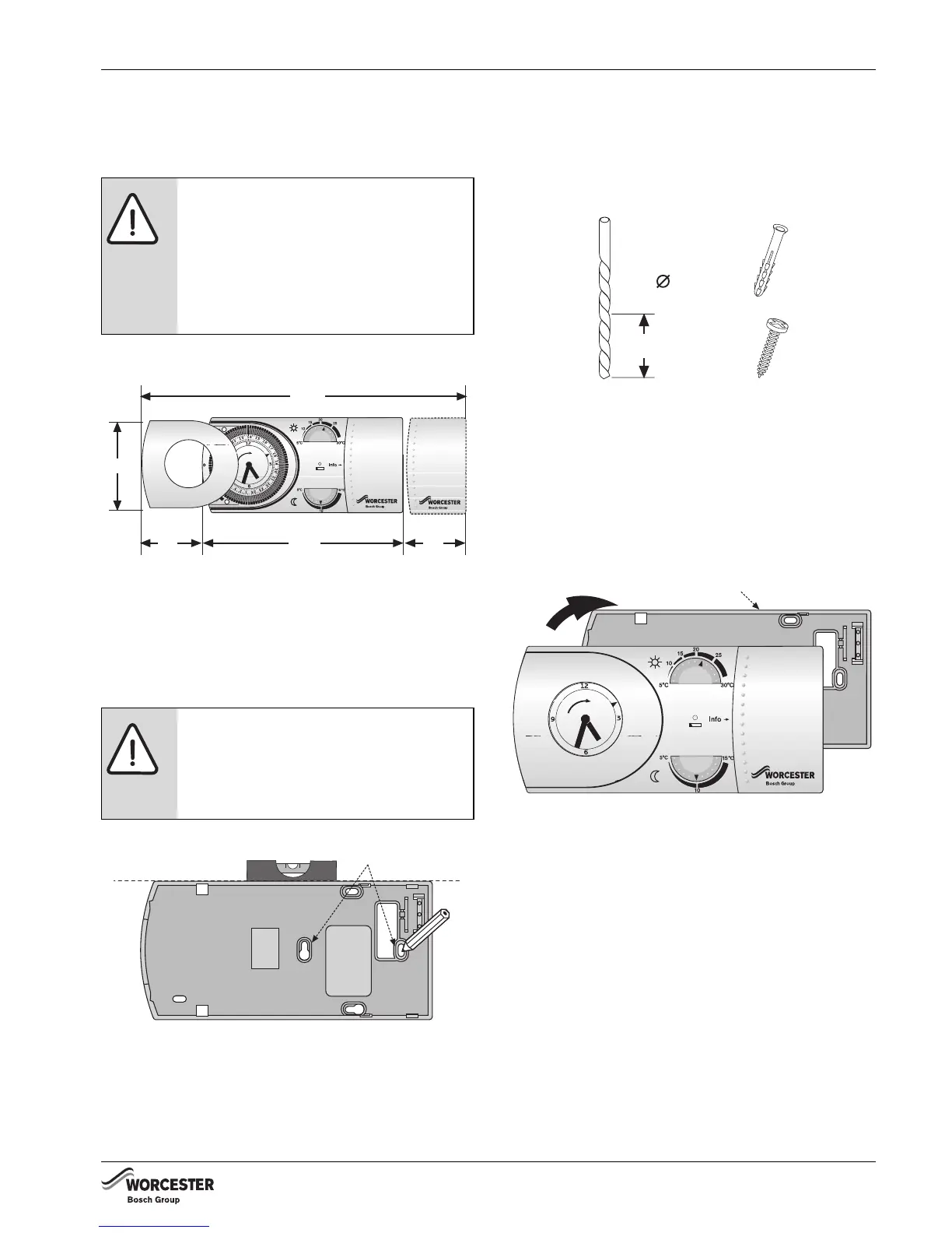
4.4 TRANSMITTER CLEARANCE &
FIXING
TRANSMITTER CLEARANCES:
Fig. 14 Transmitter clearances
See diagram above for minimum area (shown in
mm) required for operation.
TRANSMITTER FITTING:
Fig. 15 Transmitter fitting
B Hold base plate [B] level to mark securing
points [C] and remove base plate.
B Drill holes, where marked, 30mm deep using a
6mm diameter drill bit.
B Push one wall plug [D] into each hole.
Fig. 16 Fitting hardware
B Reposition base plate [B], check level and
secure with screws [E].
B Align outer edge and internal lugs of the
Transmitter to base plate [B] and push to
secure.
Fig. 17 Fitting the transmitter
NOTICE:
B All relevant safety precautions
must be undertaken.
Protective clothing, footwear,
gloves and safety goggles must
be worn as appropriate.
CAUTION:
B Ensure that there are no pipes,
electrical cables or other
hazards before drilling.
Low Batter y
Comfort
Economy
250
160 4545
75
8716115752-16.1 Wo
C
8716115752-17.1 Wo
D
E
30mm
6mm
8716115752-18.1 Wo
Low Battery
Comfort
Economy
B
8716115752-19.1 Wo

 Loading...