V5 series inverter
94
02H 02H
Data
13H
Data
13H
88H 88H
CRC CHECK Low 25H CRC CHECK Low 25H
CRC CHECK High 5CH CRC CHECK High 5CH
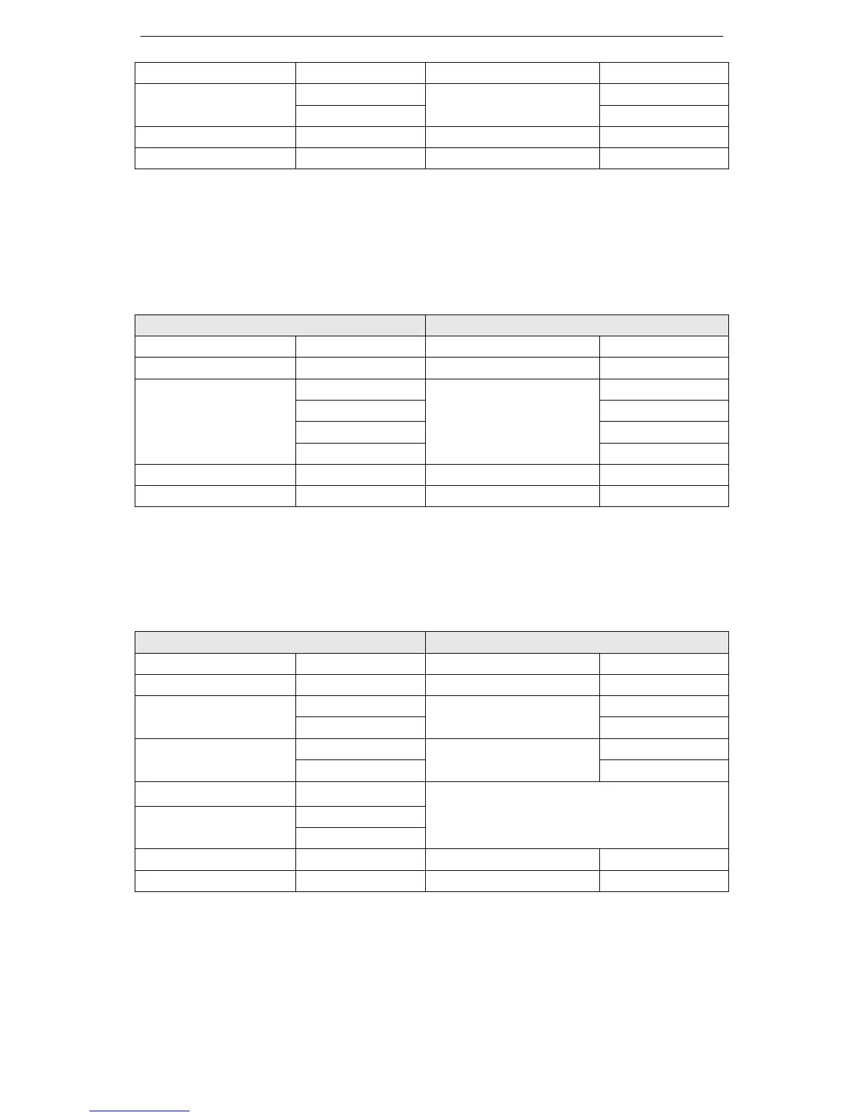
(3) Command mode: 08H circuit test
This command is used to test if the communication between the device (master) and inverter (slave) is
normal. Inverter will send the data to control device.
RTU mode:
Request mode Response mode
Address 01H Address 01H
Function code 08H Function code 08H
Data
01H
Data
01H
02H 02H
03H 03H
04H 04H
CRC CHECK Low 41H CRC CHECK Low 41H
CRC CHECK High 04H CRC CHECK High 04H
(4) Function code 10H: write multi-group data to the register
Note: V5/VB5 inverters only support one pack of data write in.
For example: write P0.06=50.00Hz in inverter address 01H.
RTU mode:
Inquiry information format Reply information format
address 01H address 01H
Function code 10H Function code 10H
Register address
00H
Register address
00H
06H 06H
Register quantity
00H
Register quantity
00H
01H 01H
Byte quantity 02H
Data
13H
88H
CRC CHECK Low ABH CRC CHECK Low E1H
CRC CHECK High 60H CRC CHECK High C8H
5. Parity code
RTU mode: Double bytes hex number
CRC field has two bytes 16-bit binary number. It is added to the message after calculating by sending
terminal. The low byte is added at first, and then is the high byte. CRC high byte is the last byte to be
 Loading...
