V5 series inverter
20
Table 2-2 Function of jumpers
Jumper Function Setup Default Setup
JP1
Pulse output terminal
DO power selection
1-2 connect: External power supply
2-3 connect: Inverter’s internal 24V power supply
External power
supply
JP2
Analog output terminal
AO output
1-2 connect: 4~20mA, AO terminal outputs current signal
2-3 connect: 0~10V, AO terminal outputs voltage signal
0~10V
JP3
CI current/voltage input
modes selection
1-2 connect : V side: 0~10V voltage signal
2-3 connect : I side: 4~20mA current signal
4~20mA
2-5-2.Terminals on control panel
1. Functions of CN1 terminal are shown in Table 2-3:
Table 2-3 Function of CN1
Type
Terminal
Mark
Name Function Description Specification
Relay output
terminal
TA
Multi-function
relay output
terminals
Multi-functional relay output
terminals. Please refer to func-
tion parameters P4.11 and de-
scription of output terminals
TA-TC: normal close
TA-TB: normal open
Contactor Capacity:
AC250V/2A (COSΦ=1)
AC250V/1A (COSΦ=0.4)
DC30V/1A
TB
TC
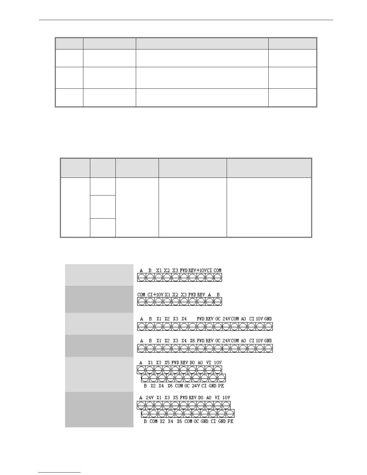
2. Control circuit terminals CN2
VB3 3-phase
0.4~0.75KW
VB5 1-phase
0.75~2.2KW
VB3 3-phase
0.75~3.7KW
VB5 3-phase
0.75~3.7KW
VB5 3-phase
5.5~7.5KW
V5 3-phase
11~55KW
Fig. 2-5 Terminals on control panel
 Loading...
