V5 series inverter
29
Save/switch In program state, press this key to enter the next menu or save the parameters.
Analog potentiometer
When P0.01=0, adjust potentiometer to change the inverter’s output frequency.
3-2-3. Fucntion description of LED and indicator
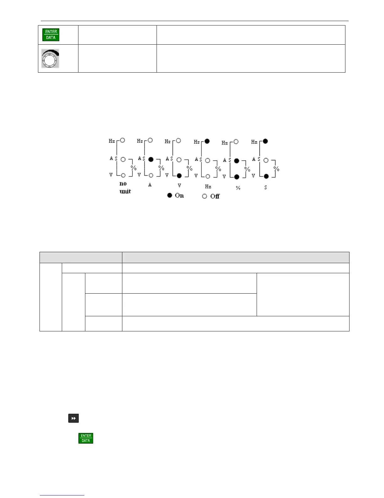
The operation panel consists of 4-bit 8-segment LED, 3 unit indicators and 3 state indicators. The three unit indicators have
6 different combinations and each combination corresponds to one unit while settting parameters.The relationship between
the combination of the indicators and the unit are shown in Fig.3-3.
Fig. 3-3 Unit represted by combination of the indicators
3 state indicators locate above the LED in the operate panel. From left to right: forward indicator FWD, reverse indicator
REV, alarm indicator ALM. The functions of these indicators are shown in Table3-1
Table 3-1 Functions of status indicators
Item Function
Display function
LED Display inverter’s current status parameters and setting parameters
State indicator
FWD
Forward running indicator, inverter outputs positive phase,
the motor will run forward after connecting to the inverter
If FWD and REV indicators all light, it
means that the inverter are in DC braking
mode
REV
Reverse running indicator, inverter outputs negative
phase.The motor will run reverse after connecting to the
inverter
ALM This indicator will light when the inverter is alarming.
3-2-4. Display of the operation panel
The inverter’s operation panel can display four parameters in stopping, editing, alarming and running.
1. Stop display
When the inverter stop, operation panel displays monitor parameters. Generally, it will display setting frequency (b-01
monitor parameter). As shown in Fig.3-4 B, the indicator on the top right displays the unit.
Pressing key can cycle display other monitor parameters in stopping status (the first seven parameters in B group
are fault displayed and the other parameters can be defined by function code P3.41 and P3.42, please refer to Chapter 5 for
details).Press to enter default display parameter b-01(setting frequency), otherwise it will always display the last
monitor parameter.
 Loading...
