V5 series inverter
22
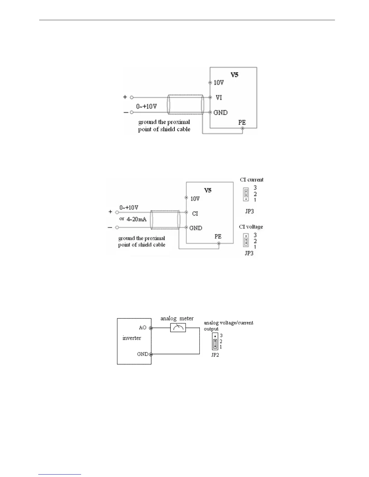
2-5-3. Analog I/O terminal wiring
1. The wiring of VI terminal voltage signal input
Fig. 2-6 VI terminal wiring diagram
2. CI terminal analog input, jumper select voltage input(0~10V) or current input(4~20mA):
Fig. 2-7 CI terminal wiring
3. Wiring for analog ouput terminal AO
Analog output terminal AO can display various physical quantities. The output voltage is 0~10V, output current is
4~20mA.
Fig. 2-8 Analog output wiring
Note:
(1) When using analog input, you can connect filter capacitor or common mode choke between VI and GND, or CI and GND.
(2) Because analog input signal is easily interfered by outside, the shield cable is required, the cable length must be short
and the shield layer must be grounded well.
 Loading...
