8
Mounting the Rotator and Antenna
Indoor Performance Check and Alignment
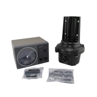
1. Temporarily connect the rotator unit and the controller using the connection cable prepared
per the previous section.
2. Check to be sure that the POWER switch on the controller is set to OFF, then plug the con-
troller’s AC cable into your station’s AC outlet.
3. Set the controller’s POWER switch to “ON”. Verify that the controller’s pilot lights have be-
come illuminated.
4. Hold down the LEFT (Left rotation) switch, and continue to hold it down until the rotator
reaches the counter-clockwise position where it automatically stops (“Left” represents
counter-clock-wise rotation when the rotator is viewed from the top).
5. When the rotator has reached the left “STOP” position, release the LEFT switch, and check
to see if the controller’s indicator needle is pointing to 0º (N: North).
If the indicator needle is out of alignment, slightly loosen the needle adjustment screw (using
a small Phillips screwdriver) on the face of the indicator, then turn the white needle adjust-
ment knob so that the indicator needle points precisely to 0º.
6. Just above the round connector jack on the rotator unit, you will observe two raised calibra-
tion marks (one each on the (rotating) bell and (xed) base of the rotator). These two marks
should be directly aligned with each other. If not, place a small piece of masking tape on
the rotating bell and the xed base of the rotator unit, and make a calibration mark on each
piece of tape to mark the current position of the bell relative to the base. This calibration
mark will be used to verify the amount of rotation in the next step.
7. Hold down the RIGHT (Right rotation) switch, and continue rotating to the right until the cal-
ibration marks (from Step 6) are again precisely aligned. Now check the indicator needle,
which should also have rotated fully 360º so as to be pointing exactly to 0º. If the indicator
needle is not pointing exactly to 0º, go to the rear panel of the controller, and set the Adjust-
ment Potentiometer Selection Switch (see Figure 2) to the right position. Now use a small
screwdriver to adjust the Indicator Needle Adjustment Potentiometer (Fig. 2) so that the in-
dicator needle points exactly to 0º.
8. After aligning the needle to 0º, set the Adjustment Potentiometer Selection Switch back to
the left position.
9. Hold down the RIGHT switch again, and continue rotation to the right. You should observe
the “OVERLAP” LED becoming illuminated as rotation passes the 360º point. If the OVER-
LAP LED does not light up at the 360º position, the Overlap LED Adjustment Potentiometer
may be used to align the illumination threshold to the 360º point.
10. Check to verify that rotation automatically stops at approximately 90º (East; representing a
total rotation range of 450º from the original starting point).
11. Press the LEFT and RIGHT rotation switches a few more times, verifying that rotation
appears to be normal. If so, press the LEFT switch to return the rotator to the fully count-
er-clockwise (0º) position.
12. At this time, you must determine whether you wish to leave the “Left Stop” position at
North,or whether you wish to set it to South (to allow uninterrupted rotation from southeast
to north-east to northwest to southwest, for example). If you wish to leave the “Stop” at
North, the checkout process is complete. If you wish to set the “Stop” to South, again loos-
en the needle adjustment screw on the face of the controller, and rotate the needle to the
“South” position.
Be certain that the rotator is fully rotated to the “LEFT” position in either case.
Advice: The position of the “Left Stop” can be set to whatever position you like (North, South,
East, or West). Just remember where you have set it, because the antenna must ini-
tially be aimed in the same direction when it is installed on the mast (see next section).
13. Turn the POWER switch OFF. This completes the ground-based testing of the rotator and
controller.

 Loading...