6
Control Cable Installation
Before installing the rotator, mast, and antenna, prepare the rotator control cable and test
rotator system performance on the ground. Potential alignment, cabling, or other problems
can quickly be resolved on the ground; once a rotator is mounted, however, troubleshoot-
ing may require that the tower be climbed and/or the rotator be removed and lowered to
the ground!
Control Cable Preparation
The control cable to be used should have six stranded conductors of at least 0.5 mm (#20
AWG) diameter if the cable is shorter than 40 m in length (125’); if the cable is longer than
40 m, use conductors with a diameter of 0.75 mm (#18 AWG) or larger.
The optional control cable “C-25MWP (25 m)” or “C-40MWP (40 m)”, are recommended
to connect the controller and the rotator.
Although C-25MWP and C-40MWP are 6 core cables, only 4 cores are used with the
G-450ADC/-450CDC.
1. Disassemble the supplied round plug: slide off the rubber boot, remove the setscrew
from the shell using a small screwdriver, then unscrew the shell from the plug. Save the
setscrew in a safe place until step 10, so you don’t lose it.
2. Slide the rubber boot and the round shell over the “rotator” end of the cable. Leave
enough cable protruding to allow easy dressing the end of the cable.
3. Using special care to avoid nicking the insulation of the individual wires, strip back 20
mm (about 25/32”) of the outer jacket of the cable from both ends. Now strip 4 mm (about
5/32”) of insulation from each wire, being careful not to nick the conductors.
4. Solder the wires to the round plug pins, noting the color of the wire and the number
associated with each pin for reference later. Pins 1, 6 and 7 of the round connector
are not used! Conrm that all solder joints are rm and cleanly made, as this part of
the cable will be difcult to access once the rotator is installed on top of the tower. Do
not slide the shell onto the connector at this time.
5. Crimp the supplied pin contacts onto the wires on the opposite end of the cable, per
the illustration on the next page.
6. Referring to your notes of the wire color at each pin of the round (rotator end) connec-
tor, insert the pins into the rectangular plug at the opposite (controller) end of the cable.
Be sure that each wire from the round connector is routed to the corresponding pin
number in the rectangular connector (i.e. 2 to 2, 3 to 3, etc.).
7. Temporarily connect the round plug to the rotator, and the rectangular plug to the con-
troller. Make sure that the POWER switch on the controller is set to “OFF”, then plug
the controller's AC cable into your station’s AC outlet.
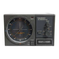
8. Set the controller's POWER switch to “ON”. The pilot lamps on the controller should
become illuminated, and the meter needle on the controller may rotate so as to align
itself with the current position of the rotator (remember, the two units have not been
aligned with each other).
9. Press the LEFT (left rotation) side of the seesaw switch, and conrm that the rotator
(when viewed from the top) and the controller’s needle turn counter-clockwise together.
Stop rotation, then press the RIGHT (right rotation) side of the seesaw switch, and con-
rm that the rotator and indicator needle turn clockwise. If rotation does not occur as
indicated, turn the POWER switch “OFF”, and re-check your cable connections.
10. If the rotator and controller are working as described, replace the plug shells, setscrew,
and rubber boot (removed in step 1).
 Loading...