page 22 MARK-V FT-1000MP Operating Manual
F
RONT
P
ANEL
C
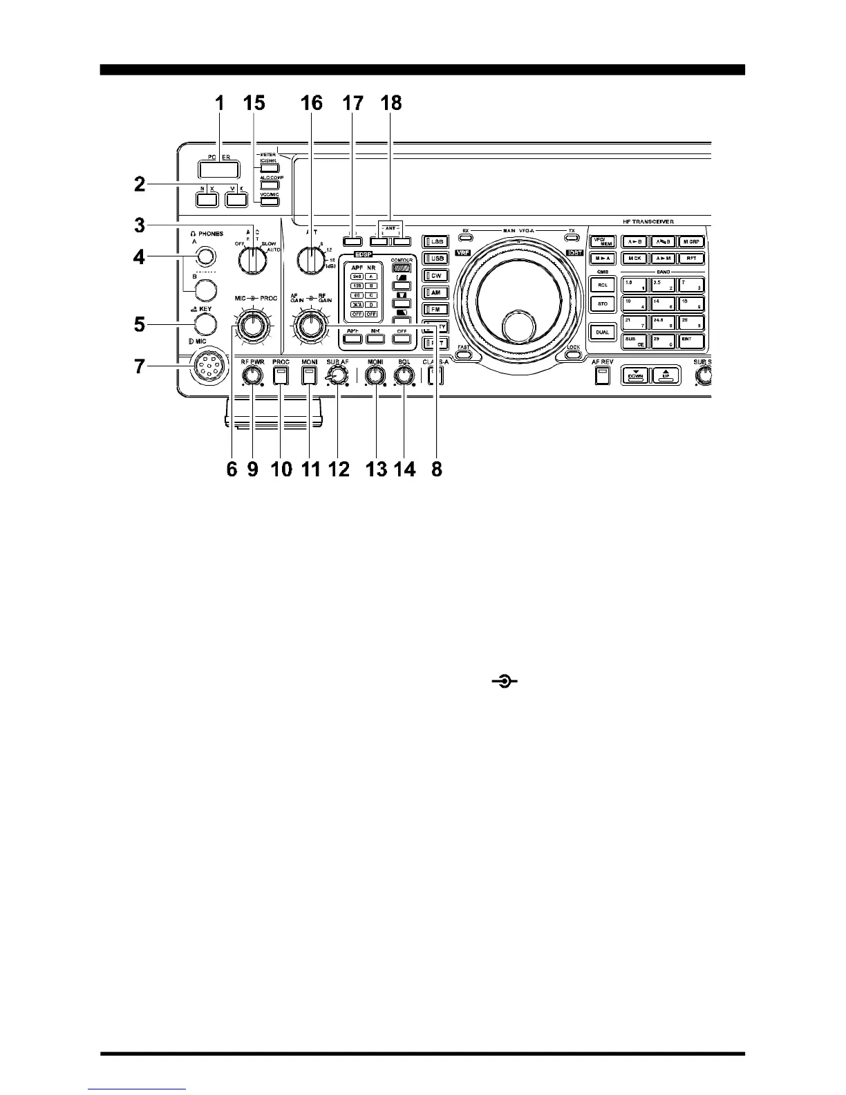
ONTROLS
1.POWER Button
This button turns the transceiver on and off.
2.MOX & VOX Buttons
[
MOX
]
may be used in place of a microphone PTT
switch or CW key to activate the transmitter, when de-
pressed. It must be in the undepressed position for
reception.
[
VOX
]
enables automatic voice-actuated transmit-
ter switching in the SSB, AM and FM modes, and “semi-
break-in” keying in CW mode. The controls affecting
VOX operation are located in the top access panel.
Menu Selection 7-5
sets the receiver recovery time dur-
ing semi-break-in CW operation.
3.AGC Selector Knob
Selects main receiver Automatic Gain Control de-
cay time for most comfortable reception, or disables
receiver AGC (off). Normally this switch is set to the
“AUTO” position. Strong signals will cause distortion if
this selector is set to “OFF.”
4.PHONES Jack
A ¼-inch and 3.5 mm, 3-contact jack accept either
monaural or stereo headphones with 2- or 3-contact
plugs. When a plug is inserted, the loudspeaker is dis-
abled. With stereo headphones such as the optional
YH-77STA, you can monitor both receiver channels at
the same time during dual reception. In this case, the
headphone HP controls (page 32) beneath the top ac-
cess panel adjust the levels for mixed, separate, or
monaural headphone operation.
5.KEY Jack
This ¼-inch, 3-contact jack accepts a CW key or
keyer paddles (for the built-in electronic keyer), or out-
put from an external electronic keyer. You cannot use
a 2-contact plug in this jack (to do so produces a con-
stant “key down” condition). Pinout is shown on page
4. Key up voltage is 5 V, and key down current is 0.5
mA. There is another jack with the same name, con-
nected in parallel with this jack, on the rear panel.
6.MIC PROC Knob
The inner MIC control adjusts the microphone in-
put level for (non-processed) SSB and AM transmis-
sion.
The outer PROC control sets the compression (in-
put) level of the transmitter RF speech processor in
the SSB modes, when activated by the button with the
same name.
7.MIC Jack
This 8-pin jack accepts input from the MH-31
B8D
Microphone. MIC connector pinout is shown on page
4. Proper microphone input impedance is 500 ~ 600
Ohms.
 Loading...