page 50 MARK-V FT-1000MP Operating Manual
When you finish your QSO, remember to press the
Clarifier RX button again to turn off the Clarifier. You
might also want to clear the offset when done.
The MARK-V FT-1000MP has an independent
Clarifier for each VFO, on every band, plus one on each
of the 99 memories. This means that Clarifier TX/RX
and offset settings are not (improperly) carried over
when you change bands or memory channels, but
rather are stored in the same condition you last set
them until you return to that VFO, band, sub receiver,
or memory again.
Clarifier Settings
There are several settings that affect Clarifier op-
eration and the way the frequency is displayed that you
should be familiar with. After understanding their rela-
tionships, you can set them as desired.
Tuning Steps -The default 10-Hz tuning steps for
the Clarifier can be changed similar to the VFO’s using
menu function 1-9
. Choose between 0.625 Hz, 1.25 Hz,
2.5 Hz, 5 Hz, 10 Hz or 20 Hz Clarifier steps.
Clarifier M-Tune - Programmed memories can be
re-tuned using the Clarifier when this is enabled (
menu
function 1-8
). We will discuss memory tuning in detail
later on.
O
PERATION
D
EALING
WITH
I
NTERFERENCE
O
FFSET
D
ISPLAY
M
ODE
The small sub-panel to the right of the MAIN VFO-
A display can be configured to show one of four differ-
ent operating parameters.
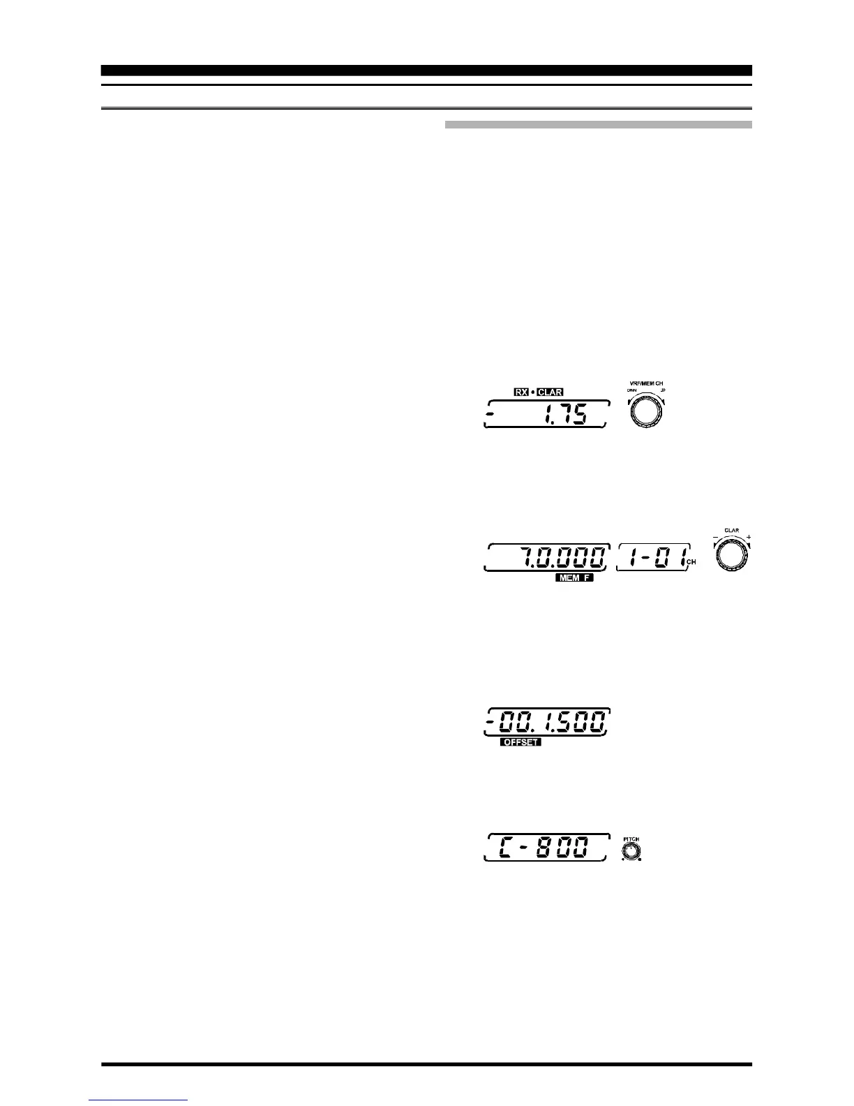
By default the Tx or Rx Clarifier offset appears.
However, this can be changed to the channel frequency,
split offset (difference between VFO-A and VFO-B), or
else the CW Pitch setting. Which display you choose,
of course, depends on your operating habits, but can
be easily changed using
menu function 3-5
. The fol-
lowing is a brief description of each display mode.
Clarifier Offset - this 3-digit display shows the Clari-
fier Tx or RX offset (±9.99 kHz) to be applied to the
operating frequency.
Channel Frequency - this displays the frequency
stored in the memory channel displayed to the right. If
the memory has not yet been stored with data, the dis-
play remains blank (except for a lone decimal point).
Offset - displays the absolute (+/–) frequency dif-
ference between MAIN VFO-A and SUB VFO-B. For
operators chasing DX stations working split, this makes
tuning “down” easier (no mental subtraction from your
operating frequency is needed).
CW Pitch - this displays the CW BFO pitch as ad-
justed by the PITCH control at the lower right corner of
the front panel.
 Loading...