En 21
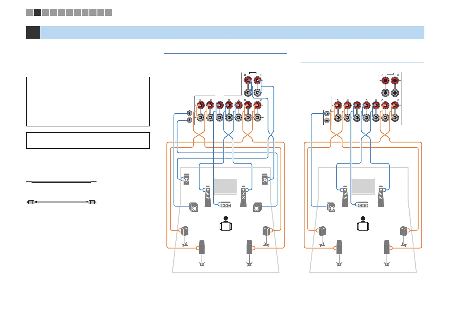
Connect the speakers placed in your room to the unit.
The following diagrams provide connections for 7.1+2-,
7.1-, and 6.1-channel systems as examples. For other
systems, connect speakers while referring to the
connection diagram for the 6.1-channel system.
Cables required for connection
(commercially available)
Speaker cables (x the number of speakers)
Audio pin cable (two for connecting two subwoofers)
7.1+2-channel system 7.1-channel system
(using surround back speakers)
2 Connecting speakers
Caution
• Remove the unit’s power cable from an AC wall outlet and turn
off the subwoofer before connecting the speakers.
• Ensure that the core wires of the speaker cable do not touch
one another or come into contact with the unit’s metal parts.
Doing so may damage the unit or the speakers. If the speaker
cables short circuit, “Check SP Wires” will appear on the front
display when the unit is turned on.
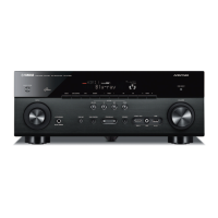
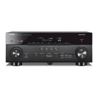
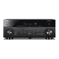
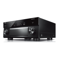
• The illustrations of the unit (rear) used in this section are of the
RX-V779.
SURROUND CENTER
CLASS 2 WIRING CABLAGE CLASSE 2
FRONT
SINGLE
SURROUND BACK/BI-AMP
SPEAKERS
SUBWOOFER
ZONE2/F.PRESENCE
EXTRA SP
1
2
1
67
2
3
45
9
9
ER
SURROUND CENTER
CLASS 2 WIRING CABLAGE CLASSE 2
FRONT
SINGLE
SURROUND BACK/BI-AMP
SPEAKERS
SUBWOOFER
ZONE2/F.PRESENCE
EXTRA SP
1
2
1
67
2
3
45
9
1 2 3 4 5 6 7 8 9 10 11
 Loading...