60
P-115B/P-115WH/P-45B
■■ DM■CIRCUIT■BOARD■CHECK■METHOD
The DM Circuit Board is provided with test points for service check purposes.
Check the test points on the DM Circuit Board if the following symptoms appear.
Symptoms■and■check■items
1) No Pilot lamp with Power SW ON --> Check items q to t sequentially.
2) No sound or distorted sound --> Check items q, y, u and OUTPUT check items.
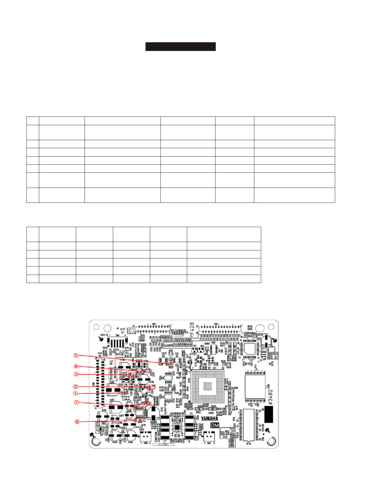
Test■Point
NO. Test Point Circuit Judgment criteria Measured by Parts with possible defects
①
+B Power supplay for DM circuit board More than 10.0V Multimeter
TR2, TH1 or D18
(On JK circuit board)
②
+5V 5 V power for digital circuit 5.0V±0.2V Multimeter IC24
③
+3.3V 3.3 V power for digital circuit 3.3V±0.1V Multimeter IC21
④
+1.2V 1.2 V power for digital circuit 1.2V±0.1V Multimeter IC20
⑤
RES CPU & memory reset signal 3.3V±0.3V Multimeter IC4
⑥
DAC-L DAC output L channel
There shall be audio
output without distortion.
Signal Checker IC23
⑦
DAC-R DAC output R channel
There shall be audio
output without distortion.
Signal Checker IC23
Note1: Use the standard AC adapter PA-150B or PA-150U for check operation.
Output
NO.
SPEAKER
OUTPUT
PHONES
OUTPUT
AUX-OUT
OUTPUT
DAC-L/R
TEST POINT
Parts with possible defects
1
× × × ×
IC1 or Error Detect Circuit
2
○ × × ×
IC23
3
× ○ ○ ○
IC1, IC22 or HP JACK
4
○ × ○ ○
IC401
5
○ ○ × ○
IC32
Note: “
○
” mark expresses normalcy and “
×
” mark expresses a failed state.
DM■Circuit■Board■(ZN321200)
Component side
P-115B/P-115WH
 Loading...