1 English
YASKAWA TOMPC71061753A YASKAWA AC Drive GA500 Installation and Operation Instruction 31
Table 1.7 Icons to Identify Screw Shapes
Icon Screw Shape
+/-
Slotted (-)
Hex socket cap (WAF: 5 mm)
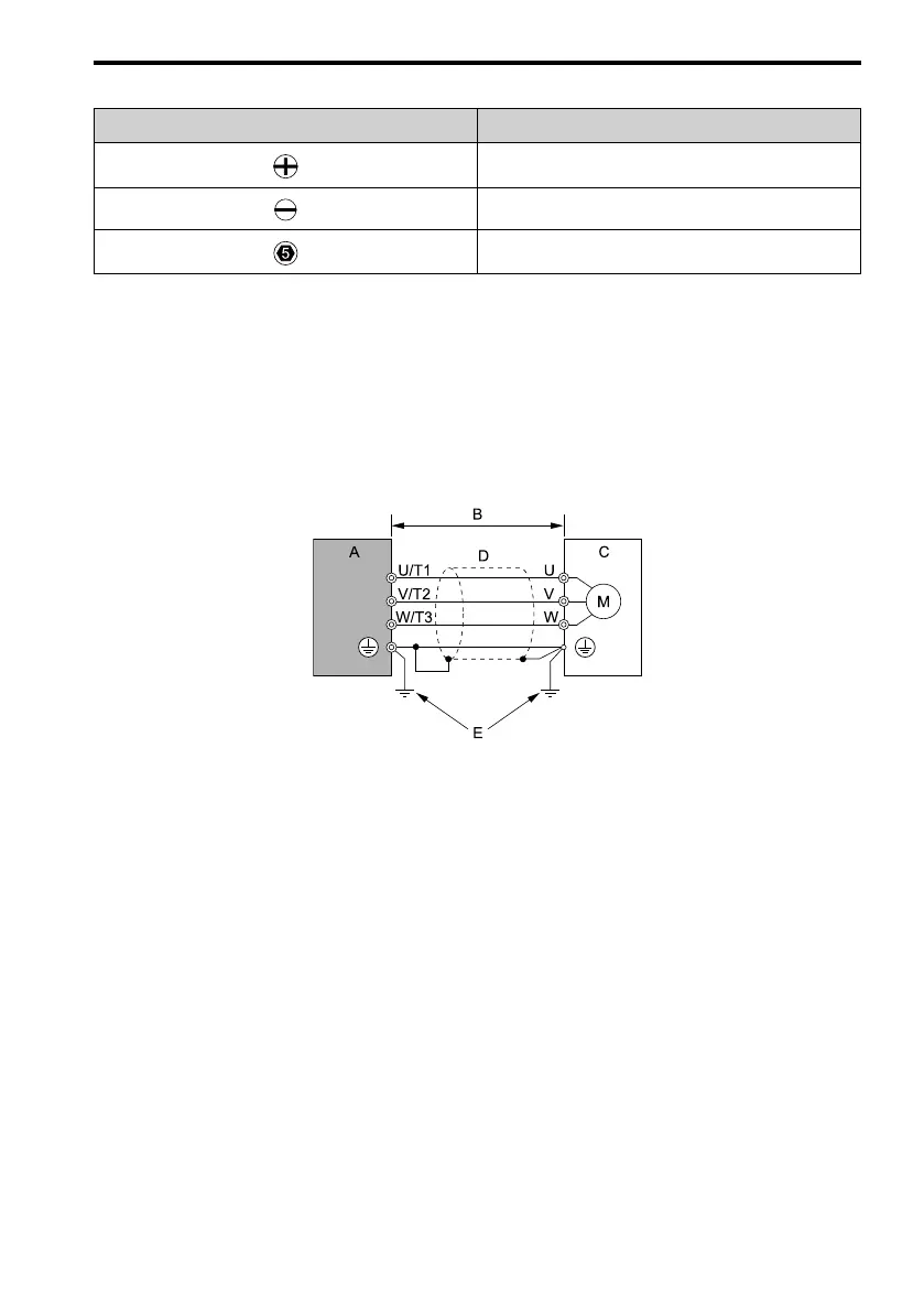
■ Install a Drive to Conform to the EMC Directive
Install drive models 2xxxE, BxxxE, and 4xxxE with this procedure to comply with the EMC
Directive when the drive is a single unit or installed in a larger device.
1. Install the drive on a grounded metal plate.
2. Wire the drive and motor.
3. Turn on the EMC filter switch.
4. Ground the wire shielding on the drive side and motor side.
A - Drive
B - Maximum wiring length
*1
C - Motor
D - Metal conduit
E - Grounding wire
Figure 1.6 Wiring the Drive and Motor
*1 The maximum wiring length between the drive and motor is: Keep the wire as
short as possible.
2xxxE, 4xxxE: 20 m (65.6 ft)
BxxxE: 10 m (32.8 ft)
5. Use a cable clamp to ground the motor cable to the metal plate.
Note:
Make sure that the protective ground wire complies with technical specifications or local safety standards.
6. Connect an AC reactor or DC reactor to decrease harmonic distortion.
Note:
To maintain compliance with IEC/EN 61000-3-2 on drive models 2001 to 2006, 4001 to 4004, install a DC
reactor.
 Loading...


