14
Notes
:
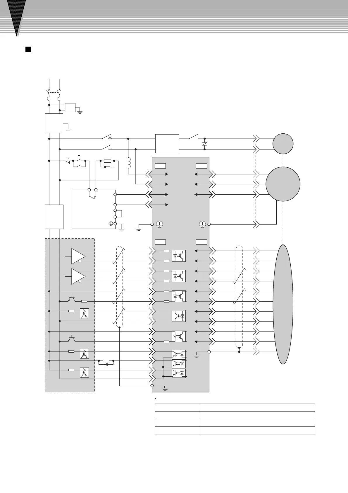
1 AVR1 : 24-VDC power supply for brake
AVR2 : 24-VDC power supply for sequence
SW1
:
Power OFF switch
SW2
:
Power ON switch
MC1
:
Magnetic contactor
Ry1
:
Relay for brake
2 The ground protection circuit is designed for ground fault inside the motor windings while the motor is running.
Therefore, it may not protect the system under the following conditions.
• A low-resistance ground fault occurs between the main circuit cable and connector for the servomotor.
• The power supply is turned ON during a ground fault.
To configure a safer system, install an earth leakage breaker to protect against both overloads and shortcircuits, or install an
earth leakage breaker for ground protection and a molded-case circuit breaker.
Manufactures of Components
Connection Diagram
Connection Diagram
Example
Spark killer
Flywheel diode
Relay for brake
Varistor
Okaya Electric Industries Co., Ltd.:
Toshiba Corp.:
Omron Corp.:
Nippon Chemi-Con Corp
.:
CRE-50500
1NH42
MY series
TNR7V121K
Power supply
Single-phase 200 V to 230 VAC
50/60Hz
AVR1
*
24-V power supply
Brake
V
W
FG
U
V
W
U
V
W
U
/Z
B
—
B
+
A
—
A
+
PG0V
PG5VCW,PULS
/CW,/PULS
CCW,SIGN
/CCW,/SIGN
CLR
/CLR
PCO
SG-PCO
+24VIN
/S-ON
ALM
/BK
/COIN
SG-COM
2
3
4
1
2
3
4
5
6
7
8
9
10
12
1
2
3
4
1
2
3
4
8
9
5
6
7
Shell
Shell
Shield
Shield
Flywheel diode
10
11
12
13
14
1L1
L2
+
2
3
1
2
3
4
5
6
7
8
9
10
1
6
5
Varistor
200 V to
230 VAC
+
24V
0V
Molded-case circuit breaker
SERVOPACK
Controller
Regenerative unit
JUSP-
RG08D
Servomotor
Encoder
Surge protector
Spark
killer
L1
SW1
MC1
MC1
Ry1
Ry1
C1 C2
+
Y4
Y5
SW2
MC1
L2
75Ω
75Ω
75Ω
75Ω
75Ω
75Ω
2.2kΩ
CNA CNB
CN1 CN2
3.4kΩ
+
24V
0V
Noise
filter
Reactor
AVR2
24-V power
supply
200 V to
230 VAC
—
—
*
:
Prepare a 24-VDC power supply
for the brake separate from the
sequence power supply.

 Loading...


