42
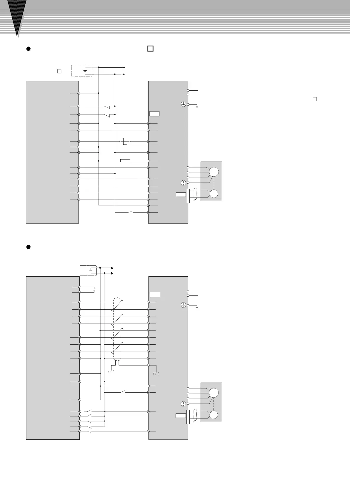
Connection to Host Controller
Connection to Host Controller
+
-
+24V
+24V
I/O power supply
SJDE SERVOPACK
L2
L1
Servomotor
0
24
V
CS1W-NC133/233/433
positioning unit
SJDE SERVOPACK
/CCW,/SIGN
CLR
/CLR
SG-PCO
CW,PULS
/CW,/PULS
CCW,SIGN
PCO
/COIN-
Twisted-pair
wires
5V power supply
for pulse output
5V GND for pulse output
Positioning completion signal
24 V power supply for output
24 V GND for output
CCW(+) output
CCW(-) output
CW(+) output
CW(-) output
Origin input signal
Origin input common
Error counter
reset output
X-axis CW limit input
X-axis CCW limit input
X-axis immediate stop input
X-axis origin proximity limit input
X-axis external interrupt input
Input common
Connector
shell
+
-
+24V
024
+24
V
V
I/O power supply
Servomotor
Notes
:
1 Omron = Omron Corporation
2 Only signals between
Yaskawa's SJDE
SERVOPACK
and Omron's CS1W-
NC133/233/433 positioning unit are shown
in the diagram.
Wiring to Mitsubishi's
QD75D
o
Positioning Unit
Wiring to Omron's CS1W-NC133/233/433 Positioning Unit
+
-
CN1
READY
CLEAR
2.2kΩ
10
9
8
4
2
1
7
12
11
6
5
/S-ON
+24VIN
10
11
6
7
8
1
12
14
18
17
15
13
16
CW,PULS
CLR
CCW,SIGN
/CW,/PULS
/CLR
/CCW,/SIGN
ALM
SG-COM
PCO
SG-PCO
2
3
CN2
L2
L1
W
V
A(1)
B
(2)
C
(3)
D
(4)
U
M
PG
CN1
A3
A5
A6
A7
A4
2
10
11
4
1
9
8
A15
A11
A14
A12
A2
A1
A8
A20
A22
A23
A21
A19
3
A24
14
7
12
5
6
+24VIN
/S-ON
SG-COM
ALM
+5V
+
-
+24V
024
+24
V
V
L2
L1
CN2
W
V
A(1)
B
(2)
C
(3)
D
(4)
U
M
PG
FLS
RLS
PG024
PGO
QD75D
positioning unit
Notes
:
1 Mitsubishi = Mitsubishi Electric Corporation
2 Only signals between
Yaskawa's SJDE
SERVOPACK
and Mitsubishi's QD75D
positioning
unit are shown in the diagram.

 Loading...


