User Constants
Bit
Description
Factory Setting
b0
SV_ON command mask
0: Enable SV_ON/SV_OFF command.
1: Always send SV_ON command (Servo ON)
0
bl
SENS_ON command mask
0: Enable SENS_ON/SENS_OFF command
1: Always send SENS_ON command (Encoder power ON)
0
b2
P-OT mask
0: Enable the P-OT signal.
1: Mask (always disable) P-OT signal
0
b3
N-OT mask
0: Enable N-OT signal.
1: Mask (always disable) N-OT signal
0
b4
—
0
b5
0
b6
Stopping method for base block
0: Dynamic brake (D13) stop
1: Coasting to a stop
0
b7
Operation after dynamic brake stop
0: Release dynamic brake.
1: Do not release dynamic brake.
1
7.3.1 Cn-0001: Memory Switches 1
7.3 Memory Switch Bit Details
The following describes each bit of memory switch (bit-type user constant).
7.3.1 Cn-0001: Memory Switches 1
• Bits b0 to b7
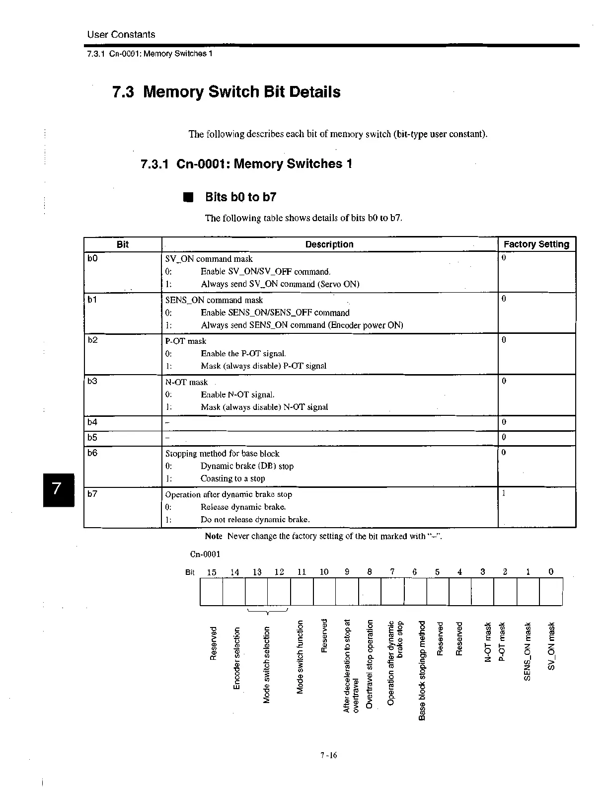
The following table shows details of bits b0 to b7.
Note Never change the factory setting of the bit marked with "—".
Cn-0001
Bit 15 14 13 12 11 10 9 8
7
6
5
4 3
2 0
O
CC
C
O
0
cu
Tu
0
C
Mode switch selection
Mode switch function
-o
O
cu
CC
Overtravel stop operation
Base block stopingp method
'0 0
CD 0
NQ)
CC m
N-OT mask
P-OT mask
SENS ON mask
SV_ON mask
7 -16
 Loading...


