YORK INTERNATIONAL
16
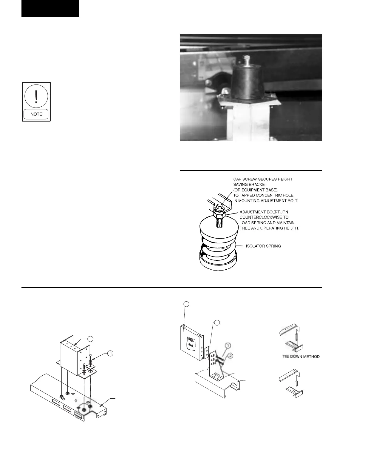
FIG. 10 – STANDARD TIE-DOWN / NO SNUBBER
FOR UNITS CP85 - CP305
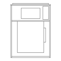
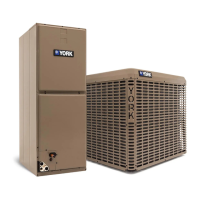
FIG. 9 – SPRING ISOLATOR
3. To adjust isolators: First loosen nuts on top of
adjustment bolt. Then turn adjustment. Next check
operational height and level of frame. Repeat this
procedure until operational height and frame is level.
Finally, tighten nuts.
It is the responsibility of the installer
to insure vibration free operation, if
isolation is not supplied by YORK.
AIR SYSTEM
All duct work should be designed and installed accord-
ing to AMCA Standards. AMCA Standard 201 re-
quires that the outlet duct be a minimum of 3 wheel
diameters long and is not greater than 107.5% nor
less than 87.5% of the fan outlet area. It also requires
that the slope of the transition elements should not be
greater than 15% for converging elements, nor greater
than 7% for diverging elements.
DUCT CONNECTION GUIDELINES
(See Figures 14 and 15)
All intake and discharge air duct connections to the unit
may be made directly to the unit with the exception of
external isolation options. These air duct connections
should be of flexible material and should be installed so
they are sufficiently loose. Duct turns and transitions
Installation
LD06333
I
LAT
R RAI
TANDARD
ET
TIE-D
W
DO NOT REMOVE
TANDARD TIE-D
WN
N
N
BBE
IN UNITS 2' HIGH INSIDE
NE TIE-D
WN WHI
H I
N
T A
E
IBLE I
N
T
TIED D
WN
REM
VE 4 B
LT
FIG. 11 – TIE-DOWN METHOD FOR UNIT
SIZES CP85 - CP1030
D
N
T REM
V
BL
WER
E
WELDED
DO NOT REMOVE
TANDARD
ET
TIE-DOWN
WELDED
I
LAT
R
REM
VE B
LT
REM
VE ANY
PA
ER
F
ND BETWEEN BL
WE
GUSSET AND GUSSET
TIE-DOWN
TIE D
WN METH
D F
NIT
IZE
THR
1
EX
EPT 12
F
R
NIT
& 12
TIE D
WN METH
F
R MIDDLE
PRIN
N
& 1
.
TAL
.
TAL
LD06497
LD06498
FIG. 8 – RUBBER-IN SHEAR ISOLATOR -
NO ADJUSTMENT
00486VIP
 Loading...