FORM 100.10-NOM2
59
YORK INTERNATIONAL
SERVICE
TROUBLESHOOTING
An HVAC air system includes the air handling unit and
the entire air circuitry through which air flows. Included
in the system are such components as duct work, fit-
tings, branch duct, dampers, heat exchangers, filters,
sound traps, coils, elbows, registers, grilles, and other
items through which air flows or which offer obstruc-
tion to air flow.
While differences in temperature and humidity may
cause air movement, it may be considered very slight in
comparison to the positive circulation required in an air
conditioning system. To accomplish this air movement,
a fan has two functions to perform.
1. To produce sufficient pressure or head to acceler-
ate the mass of air from a state of rest to the re-
quired velocity, and
2. To produce sufficient pressure to overcome any
resistances to the flow of air.
The determination of these pressures is a very impor-
tant part of troubleshooting an air conditioning system.
The generally accepted standard instrument for mea-
suring these unit pressures is the Pitot Tube. (See Fig-
ures 61 & 62) The Pitot Tube is used in conjunction
with an Inclined Manometer, Magnehelic Gauge, or a
Tube Manometer.
When the Pitot Tube is used in conjunction with these
instruments, one is able to read velocity pressure (Vp),
static pressure (Sp), and total pressure (Tp) within the
system.
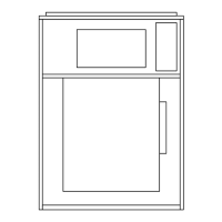
PITOT TUBE
The Pitot consists of an impact tube within a larger
static tube. When the impact tube is pointed directly
into the air stream, the small static pressure holes are
perpendicular to the air stream and are not affected by
air velocity. (See Figure 62)
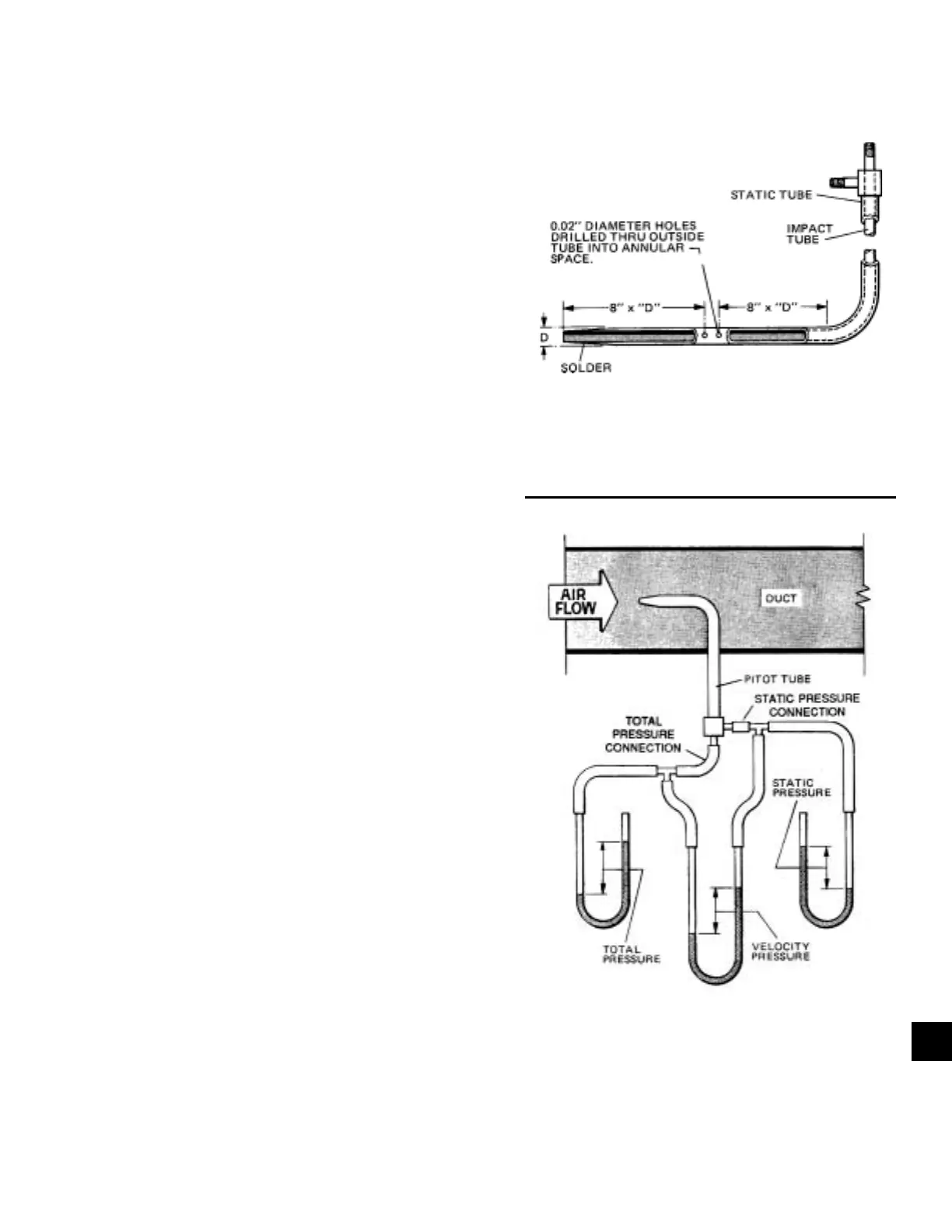
To read velocity pressure, the total pressure tap at the
end of the pitot tube is connected to one leg of a ma-
nometer and the static pressure tap at the other leg of
the manometer. (See Figure 63)
FIG. 61 – CONSTRUCTION OF PITOT TUBE
FIG. 62 – PITOT TUBE
LD06363
LD06362
5
 Loading...