127878-YIM-C-1208
Johnson Controls Unitary Products 65
UNIT CONTROL BOARD OPTION SETUP
OPTION BYTE SETUP
• Enter the Option Setup mode by pushing the OPTION
SETUP / STORE button, and holding it for at least 2 sec-
onds.
• The green status LED (Option Byte) will be turned on
and the red status LED (Heat Delay) is turned off.
• The 8, 4, 2 and 1 LEDs will then show the status of the 4
labeled options ((8) Fan Off at Heat Start, (4) Low
Ambient Lockout, (2) Free Cooling Lockout, and (1)
Lead / Lag).
• Press the UP or Down button to change the LED status
to correspond to the desired Option Setup.
• To save the current displayed value, push the OPTION
SETUP / STORE button and hold it for at least 2 sec-
onds. When the value is saved, the green LED will flash
a few times and then normal display will resume.
NOTE: While in either Setup mode, if no buttons are
pushed for 60 seconds, the display will revert to its
normal display, exiting the Option Setup mode.
When saving, the control board only saves the
parameters for the currently displayed mode
(Option Byte or Heat Delay).
HEAT DELAY SETUP
• Enter the Option Setup mode by pushing the OPTION
SETUP / STORE button, and holding it for at least 2 sec-
onds.
• The green status LED (Option Byte) will be turned on
and the red status LED (Heat Delay) is turned off.
• Press the COMM SETUP / SELECT button to toggle into
the Heat Delay Setup, the green LED will turn off and the
red LED for Heat Delay will turn on.
• The 8, 4, 2 and 1 LEDs will then show the status of the
Heat Delay, (See Table 42). Press the UP or Down but-
ton to change the LED status to correspond to the
desired Heat Delay Value.
• To save the current displayed value, push the OPTION
SETUP / STORE button and hold it for at least 2 sec-
onds. When the value is saved, the red LED will flash a
few times and then normal display will resume.
NOTE: While in either Setup mode, if no buttons are
pushed for 60 seconds, the display will revert to its
normal display, exiting the Option Setup mode.
When saving, the control board only saves the
parameters for the currently displayed mode
(Option Byte or Heat Delay).
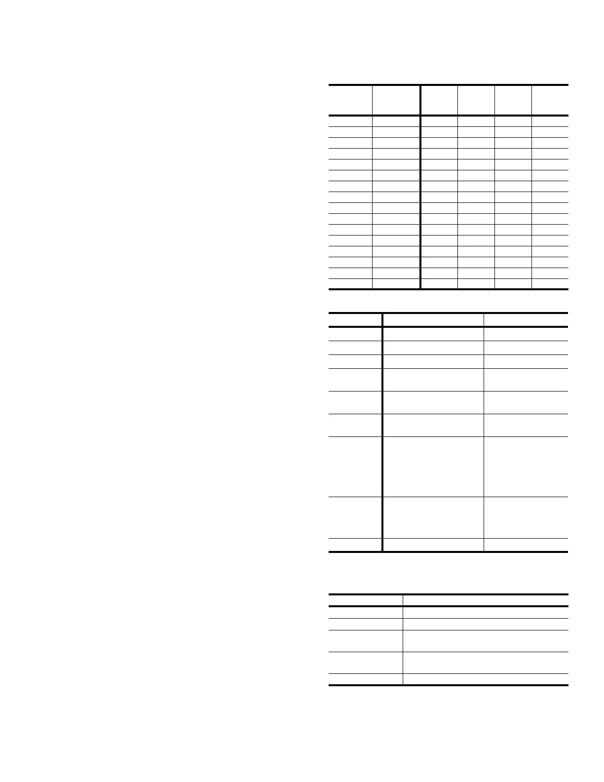
TABLE 42: HEAT DELAY
Heat
Fan On
Delay
Heat
Fan Off
Delay
Red
LED 8
Red
LED 4
Red
LED 2
Red
LED 1
60 180 On On On On
60 90 On On On Off
60 60 On On Off On
60 30 On On Off Off
45 180 On Off On On
45 90 On Off On Off
45 60 On Off Off On
45 30 On Off Off Off
30 180 Off On On On
30 90 Off On On Off
30 60 Off On Off On
30 30 Off On Off Off
060OffOffOnOn
0 30 Off Off On Off
0 10 Off Off Off On
Non-std Non-std Off Off Off Off
TABLE 43: IGNITION CONTROL FLASH CODES
FLASHES FAULT CONDITIONS CHECK
STEADY ON
Control Failure Control
HEARTBEAT
Normal Operation
1
Not Applicable
2
Pressure Switch
Stuck Closed
Pressure Switch
3
Pressure Switch Failed
To Close
Venter Pressure Switch
Vent Blocked
4
Limit Switch Open
Main Limit
AUX Limit
5
Flame Present With Gas
Off First Stage Gas Valve
Energized With W1 Off
Second Stage Gas Valve
Energized With First Stage
Gas Valve Off
Gas Valve
6
Ignition Lockout
Gas Flow
Gas Pressure
Gas Valve
Flame Sensor
STEADY OFF
No Power Or Control Failure 24VAC or Control
TABLE 44: REHEAT CONTROL BOARD FLASH
CODES
FLASH CODES DESCRIPTION
On Steady This is a Control Failure
1 Flash Not Applicable
2 Flashes
Hot Gas Reheat is on with Y1 Output
(No Call for Cooling)
3 Flashes
Y1, Y2, and Hot Gas Reheat is on because of
a call for Y1 and Humidistat. See alt operation
OFF No Power or Control Failure
 Loading...