JOHNSON CONTROLS
203
FORM 160.54-O1
ISSUE DATE: 9/10/2014
4
SECTION 4 - PRINTING
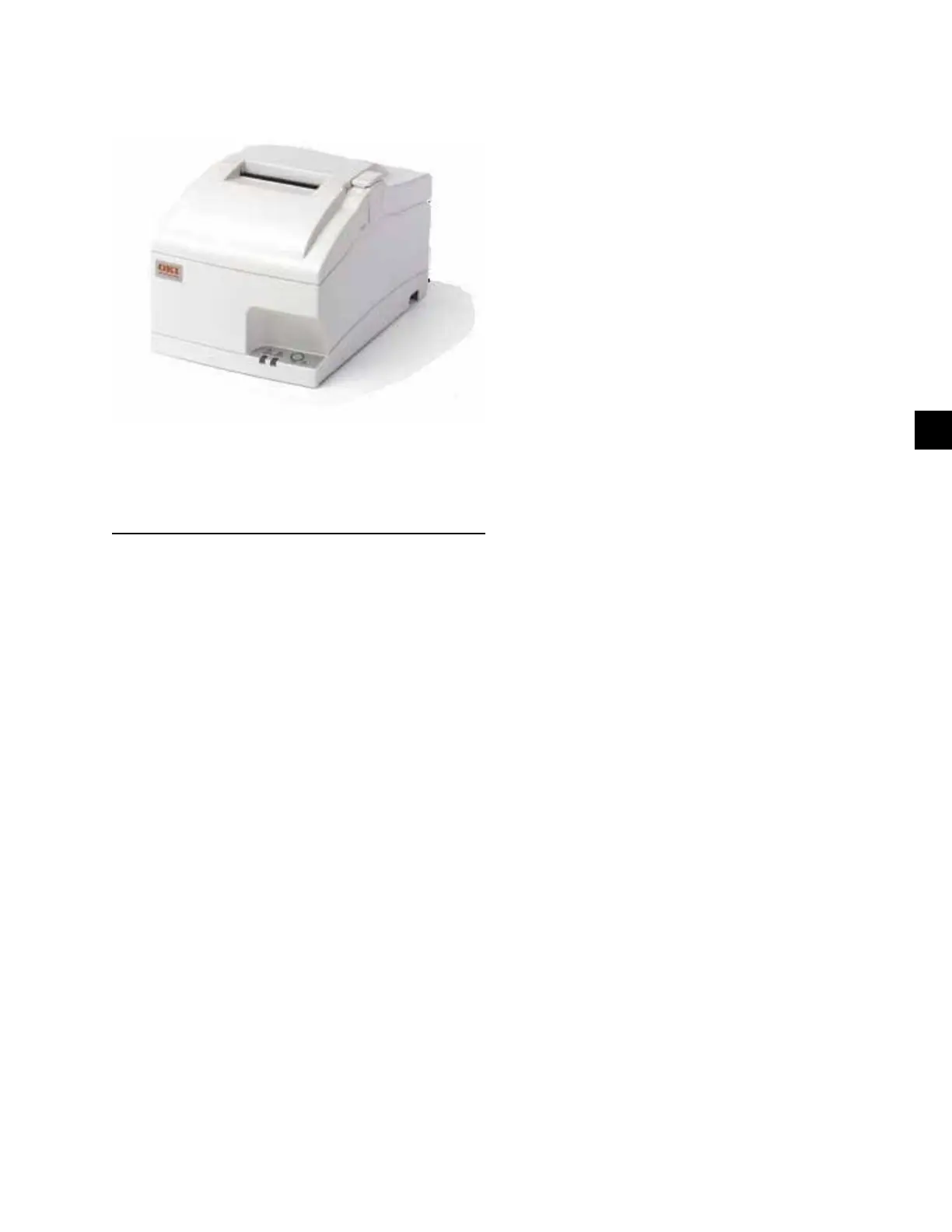
FIGURE 62 - PRINTER
LD16572
OKIPOS 441 Serial
Charcoal p/n 62113901
Beige p/n 62113601
PRINTING OVERVIEW
A printer can be connected to the Control Center’s
Microboard to print the following reports. The screen
from which each report can be generated is listed in
parenthesis.
• Status - Present system parameters (Printer, Home)
• Setpoints - Present programmed values of all set-
points (Printer, Setpoints)
• Schedule - Present value of programmed daily
schedule (Printer, Schedule)
• Sales Order - Information about SALES ORDER
Screen (Printer, Sales Order)
• History - System parameters at the time of the last
normal stop, last fault while running and last 10
faults, whether running or not (Printer, History)
• Cycling or Safety Shutdown Initiated Print -
Snapshot of all system parameters at instant of
shutdown. Automatically occurs if printer is con-
nected at time of shutdown.
• Adaptive Capacity Control (ACC) Surge Map
- System conditions at instant all surge points
were mapped. (Compressor Motor Variable Speed
Drive applications; requires SERVICE access lev-
el) (Printer, ACC)
• Trend (Flash Memory Card version
C.MLM.01.05.xxx and later) - Prints a snapshot
of the existing TREND Screen data or prints new
data collected after the TREND PRINT key is
pressed.
The printer can be permanently connected to the Con-
trol Center or connected as required to produce a report.
If permanently connected, a DATA LOGGING feature
can produce a status report automatically, beginning at
an Operator selected start time and occurring at an Op-
erator selected interval thereafter.
The following figures are examples of the different
print reports. Solid State Starter application print re-
ports shown. Electro-Mechanical Starter and Variable
Speed Drive reports are similar but print parameters
applicable to those devices.
• Figure 64 - Status on Page 208
• Figure 65 - Setpoints on Page 210
• Figure 66 - Schedule on Page 212
• Figure 67 - Sales Order on Page 212
• Figure 68 - History on Page 214
• Figure 69 - Security Log (Flash Memory Card
version C.MLM.01.06.xxx and later and “P”
compressors C.MLM.04.02.xxx and later) on
Page 216
• Figure 70 - Trend (Flash Memory Card version
C.MLM.01.05.xxx and later) on Page 216
• Figure 71 - CUSTOM Screen (If compressor
other than “P”, applies only to Flash Memory
Card C.MLM.01.04 and later) on Page 216
• Figure 72 - Adaptive Capacity Control New Map
point Report on Page 217
• Figure 73 - Adaptive Capacity Control Existing
Map points Report on Page 217
 Loading...