JOHNSON CONTROLS
36
FORM 160.67-O1
ISSUE DATE: 4/1/2015
SECTION 2 - OPTIVIEW CONTROL CENTER INTRODUCTION
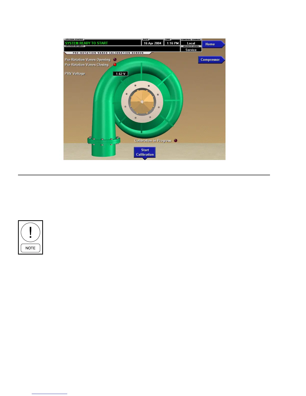
PRE-ROTATION VANES CALIBRATION SCREEN
FIGURE 12 - PRE-ROTATION VANES CALIBRATION SCREEN
00307VIP
NOTE: OptiView
™
Control Center Screens shown may NOT represent the exact screens according to the software version utilized.
OVERVIEW
This screen displays a cutaway view of the chiller com-
pressor, revealing the pre-rotation vanes and provides the
capability of calibrating the pre-rotation vanes for either
Variable Speed Drive or Hot Gas Bypass applications.
Requires a login access level of SER-
VICE. Service Technicians refer to YORK
Service Manual 160.67-M3 for opera-
tion instructions and explanation of all
programmable setpoints and displayed
values.
DISPLAY ONLY
Pre-Rotation Vanes Opening (LED)
Indicates the vanes are opening.
Pre-Rotation Vanes Closing (LED)
Indicates the vanes are closing.
Calibration in Progress (LED)
Indicates the calibration sequence is in progress.
Calibration Messages
These are text messages which step the user through the
calibration process and indicate its success or failure.
PRV Voltage
Displays the Pre-Rotation Vanes position potentiometer
feedback voltage.
PROGRAMMABLE
Start Calibration
This option is hidden after calibration has started.
Service Technicians refer to YORK Service Manual
160.67-M3 for an explanation of this setpoint.
Cancel Calibration
This option only becomes available after calibration
has started. Service Technicians refer to YORK Service
Manual 160.67-M3 for an explanation of this setpoint.
NAVIGATION
Home
Access Level Required: VIEW
Causes an instant return to the Home Screen.
Compressor
Access Level Required: VIEW
Return to the Compressor Screen.
 Loading...