Page - 28/100 AE0ZP0EC - AC-0 SSL SENSORED - User Manual
6.3 Description of power connections
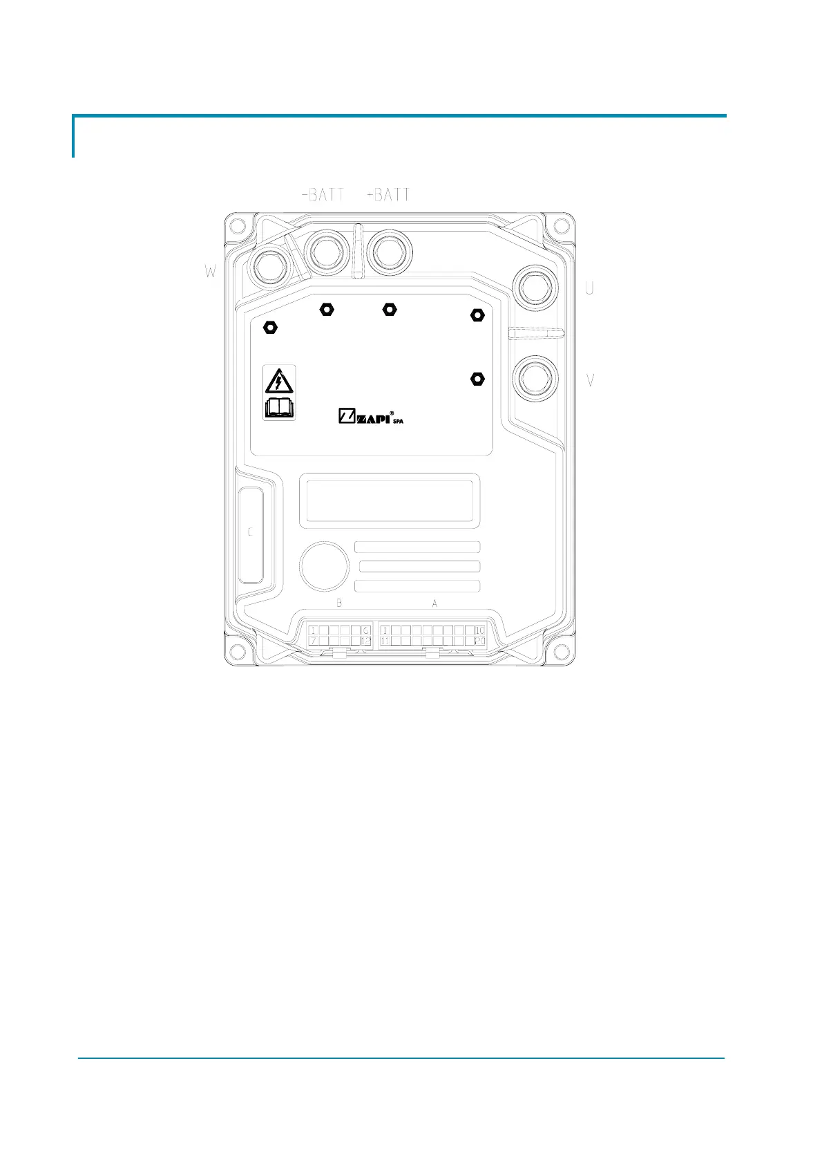
View of the power bars:
-B
INVERTER
AC-0
FW
FV
+B
FU
Figure 6–5
-B Negative of the battery.
+B Positive of the battery.
FU; FV; FW Connection bars of the three motor phases; follow this
sequence and the indication on the motor.
 Loading...
