Home
Zte
Switch
ZXR10 2910E-PS
Zte ZXR10 2910E-PS User Manual
5
of 1
of 1 rating
266 pages
Give review
Manual
Specs
To Next Page
To Next Page
To Previous Page
To Previous Page
Loading...
Chapter
5
Management
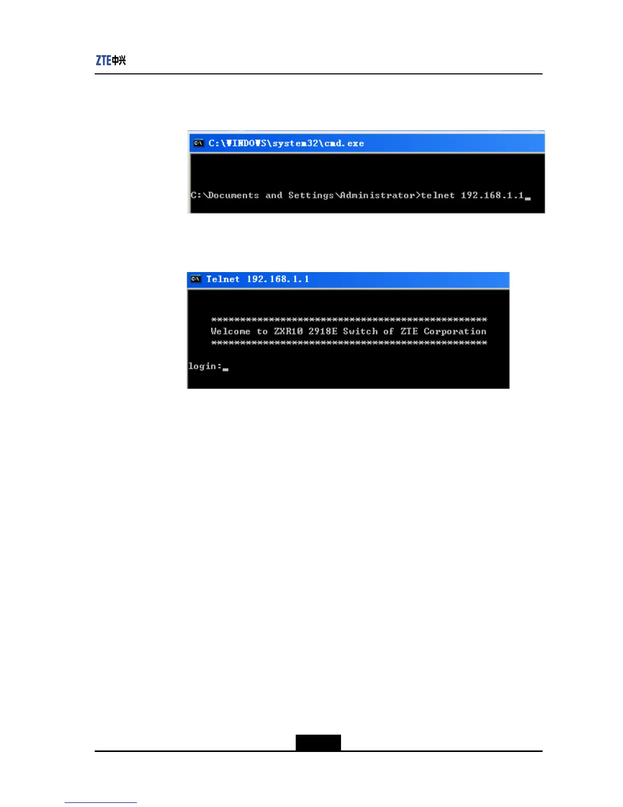
Execute
the
Telnet
command
on
the
PC,
see
Figure
5-40
.
Figure
5-40
Execute
the
T
elnet
Command
on
the
PC
For
the
T
elnet
login
result,
see
Figure
5-41
.
Figure
5-41
T
elnet
Login
Result
5-47
SJ-20120409144109-002|2012-07-02(R1.0)
ZTE
Proprietary
and
Condential
246
248
Table of Contents
Table of Contents
3
Default Chapter
1
Configuration Guide
1
About this Manual
7
Chapter 1 System Overview
9
Figure 2-1 ZXR10 2900E CONFIGURATION MODES
15
Figure 2-2 Starting Hyperterminal
16
Figure 2-3 Location Information Dialog Box
16
Chapter 2 Usage and Operation
17
Figure 2-4 Connection Description Dialog Box
17
Figure 2-5 Connect to Dialog Box
17
Figure 2-6 COM1 Properties Dialog Box
18
Figure 2-7 Run Telnet
19
Figure 2-8 Telnet Window
19
Command Modes
21
Common Command Parameters
25
Table 2-1 Common Command Parameters
26
Usage of Command Line
26
Table 2-2 Functional Keys Descriptions
28
Chapter 3 System Management
33
Configuring the TFTP Server
33
Figure 3-1 TFTPD Server
34
Figure 3-2 Tftpd Settings Dialog Box
34
Configuring the FTP Server
35
Figure 3-3 Connect to Server Dialog Box
35
Figure 3-4 Filezilla Server Window
35
Figure 3-5 Users Dialog Box
36
Figure 3-6 Directory Setting Area
36
Importing and Exporting Configuration
37
Backing up and Recovering Files
37
Downloading Software Version Automatically
38
Configuring Automatic Saving of a Configuration File
40
Figure 3-7 Network Architecture of Automatic Configuration File Downloading
40
Software Version Upgrade
41
Figure 3-8 Network Structure of Automatic Configuration File Uploading
41
File System Configuration Commands
45
Chapter 4 Service Configuration
47
Chapter 4 Service Configuration
49
Port Configuration
51
Poe Configuration
52
Figure 4-1 Poe Application
53
Port Mirroring
55
Configuration Procedure
57
Figure 4-2 Port Mirroring Configuration Instance
57
VLAN Configuration
58
Figure 4-3 VLAN Transparent Transmission Configuration Instancenetwork Topology
60
MAC Table Operation
60
LACP Configuration
63
Figure 4-4 LACP Configuration Instance
65
IGMP Snooping Configuration
66
Figure 4-5 Network Topology of IGMP Snooping Configuration Instance
69
MLD Snooping Configuration
70
Figure 4-6 MLD Snooping Configuration Instance
71
IPTV Configuration
72
Configuration Description
76
Configure Vlan
76
Figure 4-8 IPTV Configuration Instance 2
77
STP Configuration
78
Figure 4-9 MSTP Topological Structure
80
Table 4-1 Port Role and Port State
80
Figure 4-10 STP Configuration Instance
83
Figure 4-11 RSTP Configuration Instance
84
Figure 4-12 MSTP Configuration Instance
85
ACL Configuration
88
Figure 4-13 ACL Configuration Instance
95
Qos Configuration
96
Figure 4-14 Qos Configuration Instance
101
PVLAN Configuration
102
Figure 4-16 PVLAN CONFIGURATION EXAMPLE 2
104
Layer 2 Protocol Transparent Transmission Configuration
105
Figure 4-17 Layer 2 Protocol Transparent Transmission Configuration Topology
106
Ipv4 Layer 3 Configuration
107
Ipv6 Layer 3 Configuration
109
Figure 4-18 Layer-3 Configuration Instance
109
DAI Configuration
110
Figure 4-19 DAI Configuration Instancetopology
111
Access Service Configuration
112
Figure 4-20 USING PAP MODE for IDENTITY AUTHENTICATION
114
Figure 4-21 USING CHAP MODE for IDENTITY AUTHENTICATION
115
Figure 4-22 USING EAP MODE for IDENTITY AUTHENTICATION
115
Figure 4-23 Access Authentication Configuration Instance
119
MAC Authentication Configuration
120
Qinq Configuration
121
Figure 4-24 TYPICAL QINQ NETWORKING
121
Figure 4-25 Qinq Configuration Instance
122
Syslog Configuration
123
Table 4-2 Syslog Log Information
123
NTP Configuration
124
GARP/GVRP Configuration
126
Figure 4-26 GVRP Configuration Instance
127
DHCP Configuration
128
Figure 4-27 DHCP Snooping/Option82 Configuration Instancetopology
131
Figure 4-28 DHCP Client Configuration Instancetopology
132
Configuring Dhcp Client
132
Dhcpv6 Configuration
133
Figure 4-29 Dhcpv6 Snooping/Option82 Configuration Instance
135
VBAS Configuration
136
Figure 4-30 VBAS Typical Network
136
Figure 4-31 VBAS Configuration Instancetopology
137
Pppoe-PLUS Configuration
138
Figure 4-32 PPPOE-PLUS Configuration Instancetopology
138
ZESR Configuration
139
Figure 4-33 ZESR Running State When the Ring Is "Complete State
140
Figure 4-34 ZESR Running State When the Ring Is "Link Failure
141
Figure 4-35 ZESR Running State When the Ring Is "Link Restore
142
Figure 4-36 Multi-Ring Multi-Domain
142
Figure 4-37 ZESR Multi-Ring Multi-Domain Design Figure
143
Figure 4-38 Non Level 0 Segment Link
143
Figure 4-39 SMART-LINK
144
Figure 4-40 Tangent Ring Design Figure
145
Figure 4-41 ZESR Single Ring Networking
148
Figure 4-42 ZESR Multi-Ring Networking Topology
150
Chapter 4 Service Configuration
151
Figure 4-43 Smart Link Networking
153
Figure 4-44 Cross-Device TCN Sending Example
156
OAM Configuration
157
Figure 4-45 Remote Loop Network
159
Figure 4-46 Link Control Network
162
Sqinq Configuration
163
VLAN Mapping Configuration
165
Figure 4-47 VLAN Mapping Networking Diagram
166
Sflow Configuration
168
Figure 4-48 VLAN Mapping Configuration Instance
168
PP Configuration
169
LLDP Configuration
171
Figure 4-49 PP Configuration Instance
171
Figure 4-50 LLDP Configuration Instance
173
Single Port Loop Detection Configuration
174
Figure 4-51 Single Port Loop Detection Configuration Topology
176
Figure 4-52 Double Ports Loop Detection Configuration Topology
176
UDLD Configuration
177
TACACS+ Configuration
179
Figure 4-53 UDLD Configuration Instance
179
Time Range Configuration
181
Figure 4-54 TACACS+ Configuration Instance
181
Voice VLAN Configuration
182
Figure 4-55 Voice VLAN Configuration Instance
183
AG Configuration
184
Figure 4-56 Single Management Domain
184
Figure 4-57 Domains in the Network
185
Figure 4-58 Single-Domain CFM Network Without MIP
188
Figure 4-59 Single-Domain CFM Network with MIP
189
Configuration
190
Figure 4-60 LM Network Configuration Instance
191
Figure 4-61 DM Network Configuration Instance
192
Figure 4-62 AIS/LCK Network Configuration Instance
194
MAC-Based VLAN Command Configuration
195
DHCP Relay Configuration
196
Figure 4-63 DHCP Relay Configuration Instance
198
Chapter 5 Management
203
Ssh
203
Figure 5-1 SSH CONFIGURATION EXAMPLE
204
Figure 5-2 SETTING IP ADDRESS and PORT NUMBER of the SSH
204
Figure 5-3 SETTING SSH VERSION NUMBER
205
Figure 5-4 USER CONFIRMATION REQUIRED in the FIRST LOGIN
205
Privilege
206
Figure 5-5 SSH LOGIN RESULT
206
SNMP Overview
207
RMON Overview
212
Figure 5-6 MAC Change Advertisement Configuration Instance
212
Switch Configuration
214
Zgmp
215
Figure 5-7 CLUSTER MANAGEMENT NETWORKING
216
Figure 5-8 Switch Character Switch Rule
217
Figure 5-9 CLUSTER MANAGEMENT NETWORKING
220
Sflow
222
Figure 5-10 System Login Interface
224
Figure 5-11 System Main Interface
224
Figure 5-12 System Information Page
225
Figure 5-13 Port State Information Page
226
Figure 5-14 Port Configuration Information Page
227
Figure 5-15 Single Port Configuration Page
228
Figure 5-16 Bulk Port Configuration Page
229
Figure 5-17 VLAN Information Page
229
Figure 5-18 VLAN Number Entering Page
230
Figure 5-19 Single VLAN Configuration Page
231
Figure 5-20 Bulk VLAN Configuration Page
231
Figure 5-21 PVLAN Information Page
232
Figure 5-22 PVLAN Configuration Page
233
Figure 5-23 Mirror Information Page
234
Figure 5-24 Mirroring Port Configuration Page
234
Figure 5-25 LACP Basic Attribute Page
235
Figure 5-26 Bulk Aggregation Port Configuration Page
236
Figure 5-27 Aggregation Group Information Page
236
Figure 5-28 Aggregation Group Configuration Page
237
Figure 5-29 Terminal Log Information Page
238
Figure 5-30 Port Statistics Information Page
238
Figure 5-31 Configuration Information Page
239
Figure 5-32 Saving Configuration Page
240
Figure 5-33 Reboot Function Page
240
Figure 5-34 File Upload Page
241
Figure 5-35 Browse and Select the File
241
Figure 5-36 User Management Page
242
Figure 5-37 Adding User Page
243
Figure 5-38 Deleting User Page
243
M_Button
243
Telnet
245
Figure 5-39 Telnet Login Instance
246
Figure 5-40 Execute the Telnet Command on the PC
247
Figure 5-41 Telnet Login Result
247
Chapter 6 Maintenance
249
Routine Maintenance
249
Table 6-1 Maintenance Period of Ethernet Switch
250
Virtual Line Detection
250
Common Fault Handling
251
Introduction to Common Fault
251
The Configuration by Console Port Fails
251
Failed Telnet Connection
252
WEB Management Cannot be Connected
252
Losing the Login Username or Password
253
Losing Enable Enable Password
254
The Solution to Authentication Timeout Fault in Campus Network
255
The Two Devices Cannot Interconnect in the same VLAN
255
The Solution to ARP Attack in Campus Network
257
Figures
259
5
Based on 1 rating
Ask a question
Give review
Questions and Answers:
Need help?
Do you have a question about the Zte ZXR10 2910E-PS and is the answer not in the manual?
Ask a question
Zte ZXR10 2910E-PS Specifications
General
Brand
Zte
Model
ZXR10 2910E-PS
Category
Switch
Language
English
Related product manuals
Zte ZXR10 2918E
266 pages
Zte ZXR10 2918E-PS
266 pages
Zte ZXR10 2920
341 pages
Zte ZXR10 2928
341 pages
Zte ZXR10 2928E
266 pages
Zte ZXR10 2952E
266 pages
Zte ZXR10 2928E-PS
266 pages
Zte ZXR10 2900 Series
262 pages
Zte ZXR10 2900E Series
750 pages
Zte ZXR10 5250-28TC
708 pages
Zte ZXR10 5250-28SM
708 pages
Zte ZXR10 5900 Series
208 pages
 Loading...