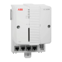
Section 2 Installation Installing the PM861/PM864/TP830 Processor Unit in Redundant
3BSE 027 941 R301 65
5. TP830 Baseplates cable connections:
a. Connect the power leads to both CPUs and the power supervision signals
from SS822 to screw terminals SA and SB (see Figure 15 on page 60).
b. Connect the Control Network cables to CN1 (single bus connection) or
CN1 + CN2 (redundant bus connection). The Control Network is
connected to both CPUs.
c. Connect the Control Builder to COM4 with cable TK212 of the Primary
CPU (if required for changing an IP address etc.). Otherwise connect the
Control Builder to the Control Network.
6. Connect the optical ModuleBus to the optical contacts on the processor units
(see Figure 2 on page 29 and Figure 17 on page 77). Information regarding
optical cable selection and cable length is provided in the S800 I/O
documentation, (see Related Documentation on page 17).
7. The CPUs are supplied with internal back-up batteries. When the batteries are
to be used, place them in the Internal Battery Holder (Figure 33 on page 121).
When the external SB821 battery units are to be used, install them according to
the instructions in Installing the SB821 External Battery Unit on page 85.
Both CPUs must be powered from the same supply (single or redundant).
For redundant power supply, see Figure 20 on page 82.
Connection to the optical ModuleBus is identical to that for the processor unit
and for the FCI in S800 I/O (Figure 29 on page 98).
Do not place the internal back-up battery in the battery holder until the AC
800M Controller has been powered-up normally and the memory back-up
function has been activated. If no normal power supply is connected to the
processor unit with the battery in place, then the CPU memory will
immediately start to consume battery power.
Always install a fresh internal or external battery at the end of the installation
phase. The original battery is heavily utilized due to frequent blackouts during
system installation.

 Loading...


