
 Loading...
Do you have a question about the ABB AC500 Series and is the answer not in the manual?
| Modular Design | Yes |
|---|---|
| Protection Class | IP20 |
| Series | AC500 |
| Mounting Type | DIN rail |
| Programming Software | Automation Builder |
| Communication Interfaces | Ethernet, Serial |
| Digital Inputs | Available |
| Digital Outputs | Available |
| Analog Inputs | Available |
| Analog Outputs | Available |
| Digital Input Voltage | 24V DC |
| Digital Output Voltage | 24V DC |
| Analog Input Type | Voltage, Current, RTD, Thermocouple |
| Analog Output Type | Voltage, Current |
| Protection | Short-circuit |
| CPU | Various models available |
| Digital I/O | Expandable |
| Analog I/O | Expandable |
| Power Supply | 24V DC |
| Certifications | CE, UL, cUL, ATEX |
| Memory | Depends on CPU model |
Procedure for assembling the AC522 module.
Procedure for disassembling the AC522 module.
Wiring and terminal assignments for the AC522 module.
Procedure for assembling the AI523 module.
Procedure for disassembling the AI523 module.
Wiring and terminal assignments for the AI523 module.
Procedure for assembling the AI531 module.
Procedure for disassembling the AI531 module.
Wiring and terminal assignments for the AI531 module.
Procedure for assembling the AI581-S module.
Procedure for disassembling the AI581-S module.
Wiring and terminal assignments for the AI581-S module.
Procedure for assembling the AO523 module.
Procedure for disassembling the AO523 module.
Wiring and terminal assignments for the AO523 module.
Procedure for assembling the AX521 module.
Procedure for disassembling the AX521 module.
Wiring and terminal assignments for the AX521 module.
Procedure for assembling the AX522 module.
Procedure for disassembling the AX522 module.
Wiring and terminal assignments for the AX522 module.
Procedure for assembling the CD522 module.
Procedure for disassembling the CD522 module.
Wiring and terminal assignments for the CD522 module.
Procedure for assembling the CI541-DP module.
Procedure for disassembling the CI541-DP module.
Wiring and terminal assignments for the CI541-DP module.
Procedure for assembling the CI542-DP module.
Procedure for disassembling the CI542-DP module.
Wiring and terminal assignments for the CI542-DP module.
Procedure for assembling the CI5x1 module.
Procedure for disassembling the CI5x1 module.
Wiring and terminal assignments for the CI5x1 module.
Procedure for assembling the CI5x2 module.
Procedure for disassembling the CI5x2 module.
Wiring and terminal assignments for the CI5x2 module.
Procedure for assembling the CM582-DP module.
Procedure for disassembling the CM582-DP module.
Connection overview for the CM582-DP module.
Procedure for assembling the CM589-PNIO(-4) module.
Procedure for disassembling the CM589-PNIO(-4) module.
Connection overview for the CM589-PNIO(-4) module.
Procedure for assembling the DA501 module.
Procedure for disassembling the DA501 module.
Wiring and terminal assignments for the DA501 module.
Procedure for assembling the DA502 module.
Procedure for disassembling the DA502 module.
Wiring and terminal assignments for the DA502 module.
Procedure for assembling the DC522 module.
Procedure for disassembling the DC522 module.
Wiring and terminal assignments for the DC522 module.
Procedure for assembling the DC523 module.
Procedure for disassembling the DC523 module.
Wiring and terminal assignments for the DC523 module.
Procedure for assembling the DC532 module.
Wiring and terminal assignments for the DC532 module.
Wiring and terminal assignments for the DI524 module.
Wiring and terminal assignments for the DI581-S module.
Wiring and terminal assignments for the DO524 module.
Wiring and terminal assignments for the DO526 module.
Wiring and terminal assignments for the DX522 module.
Wiring and terminal assignments for the DX531 module.
Wiring and terminal assignments for the DX581-S module.
Wiring and terminal assignments for the PD501-4CH module.
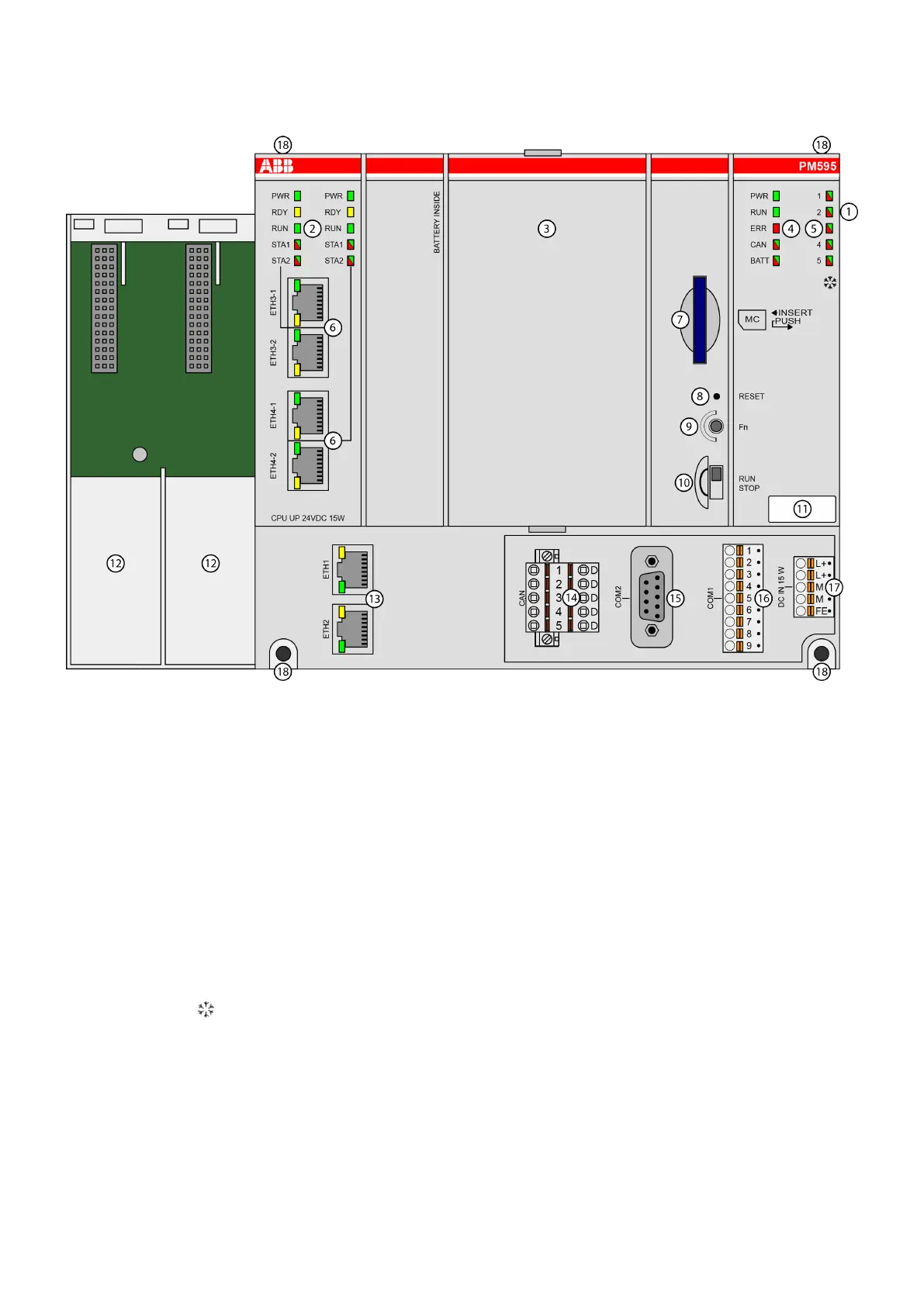
Connection overview for the PM595 module.
Connection overview for the PM56xx-2ETH module.
Connection overview for the PM5xx (-y) module.
Connection overview for the TB56xx-2ETH terminal base.
Connection overview for the TB51x-TB54x terminal base.
Connection overview for the TU582-S terminal unit.
Connection overview for the TU5xx terminal base.


