34.5 Connection
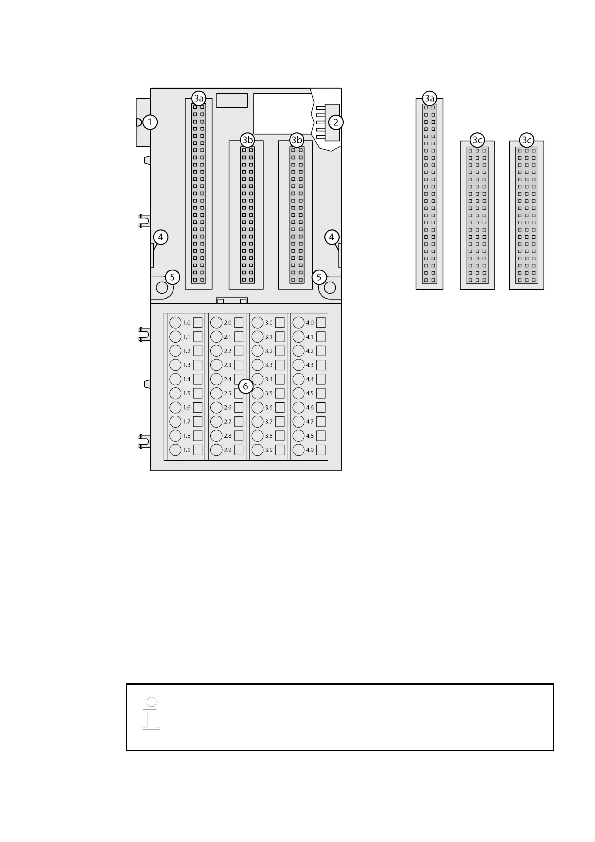
Fig. 39: TU516 for example
1 I/O bus (10 pins, male) to electrically connect the previous terminal unit, the CPU terminal
base or the communication interface module to the terminal unit
2 I/O bus (10 pins, female) to electrically connect other terminal units
3a Plug (2x 25 pins) to electrically connect the inserted I/O modules
3b For TU515, TU516(-H)(-XC), TU541 and TU542(-H)(-XC): Plug (2x 19 pins) to electrically
connect the inserted I/O modules
3c For TU531 and TU532(-H)(-XC): Plug (3x 19 pins) to electrically connect the inserted I/O
modules
4 With a screwdriver inserted in this place, the terminal unit and the adjacent terminal unit can
be shoved from each other
5 Holes for wall mounting
6 40 screw terminals or spring terminals for signals and process supply voltage
34.6 Cleaning
Cleaning instruction
Do not use cleaning agent for cleaning the device.
Use a damp cloth instead.
2019/11/153ADR024117M02xx, 11, en_US260

 Loading...


