9.4 Connection
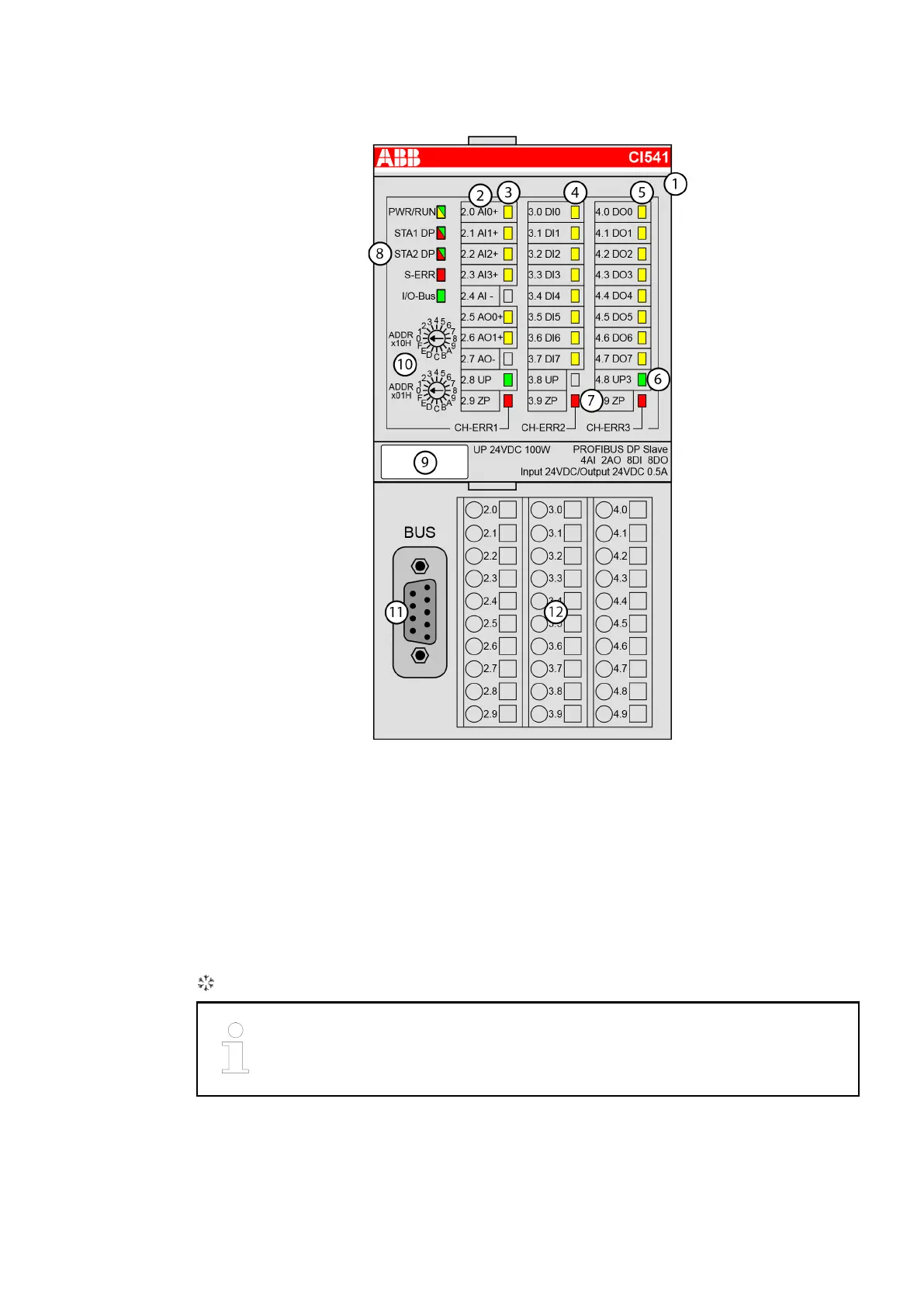
1 I/O bus
2 Allocation between terminal number and signal name
3 6 yellow LEDs to display the signal states of the analog inputs/outputs
(AI0 - AI3, AO0 - AO1)
4 8 yellow LEDs to display the signal states of the digital inputs (DI0 - DI7)
5 8 yellow LEDs to display the signal states of the digital outputs (DO0 - DO7)
6 2 green LEDs to display the supply voltage UP and UP3
7 3 red LEDs to display errors (CH-ERR1, CH-ERR2, CH-ERR3)
8 5 system LEDs: PWR/RUN, STA1 DP, STA2 DP, S-ERR, I/O-Bus
9 Label
10 2 rotary switches for setting the PROFIBUS ID
11 Interface for PROFIBUS
12 Terminal unit
Sign for XC version
All I/O channels (digital and analog) are protected against reverse polarity,
reverse supply and continuous overvoltage up to 30 VDC.
2019/11/15 3ADR024117M02xx, 11, en_US 75

 Loading...


